
Telescoping Cable Pulling Device

a telescopic and cable pulling technology, applied in the direction of cable installation, electrical equipment, electrical cables, etc., can solve the problems of worker imbalance, risk of injury, and workers' safety at risk, and achieve the effect of safe pulling cables and wires and convenient and convenient solution

Pending Publication Date: 2022-04-28
HARRELL JAMES
View PDF0 Cites 0 Cited by
  • Summary
  • Abstract
  • Description
  • Claims
  • Application Information

AI Technical Summary

Benefits of technology

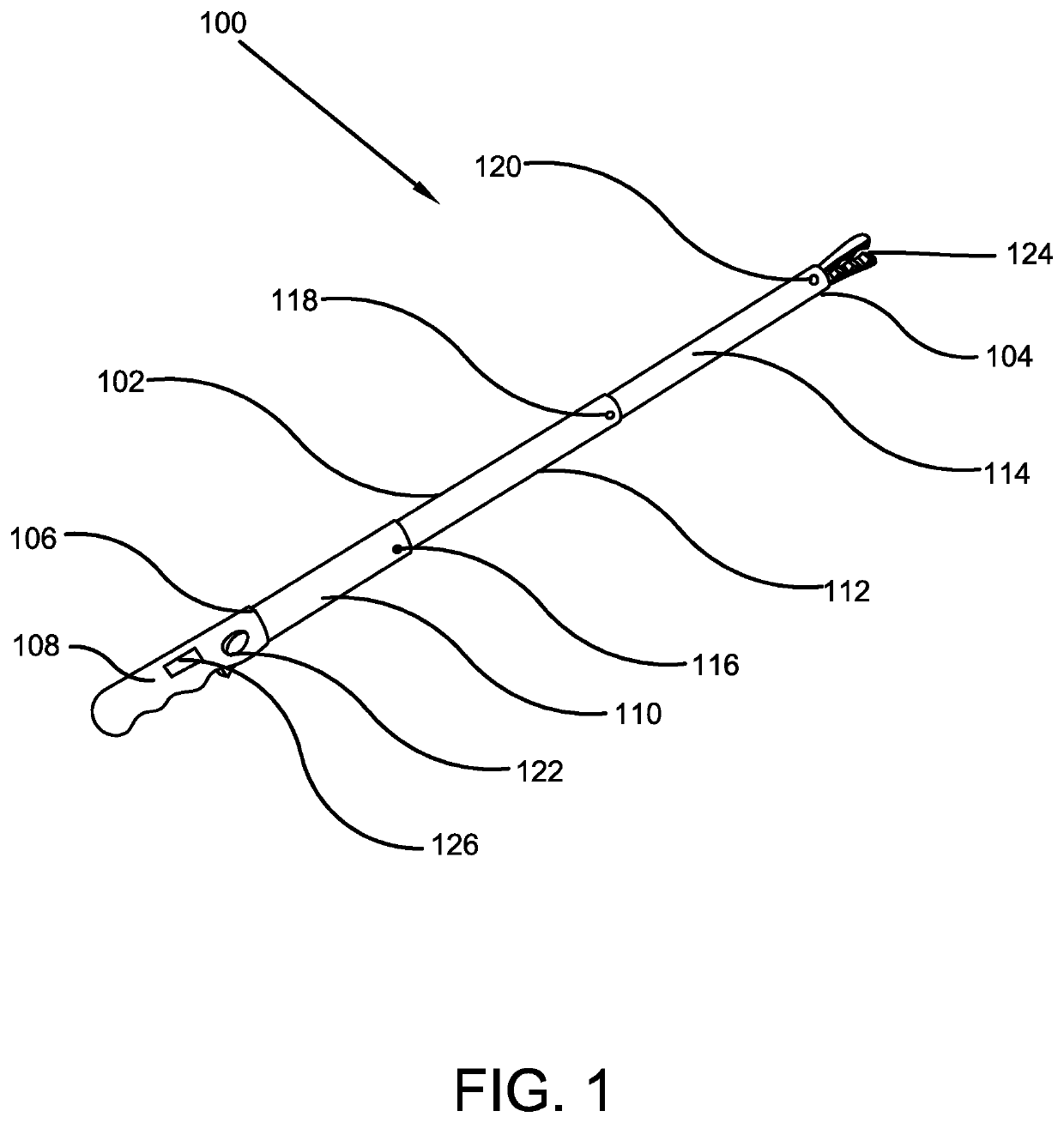
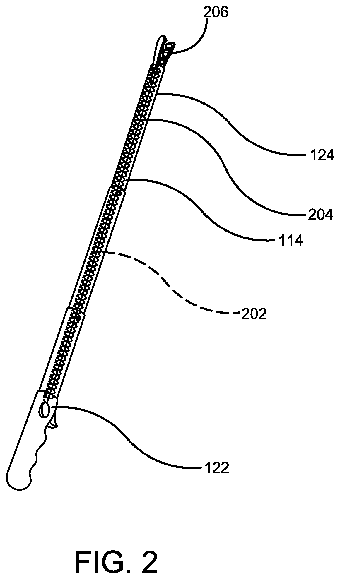
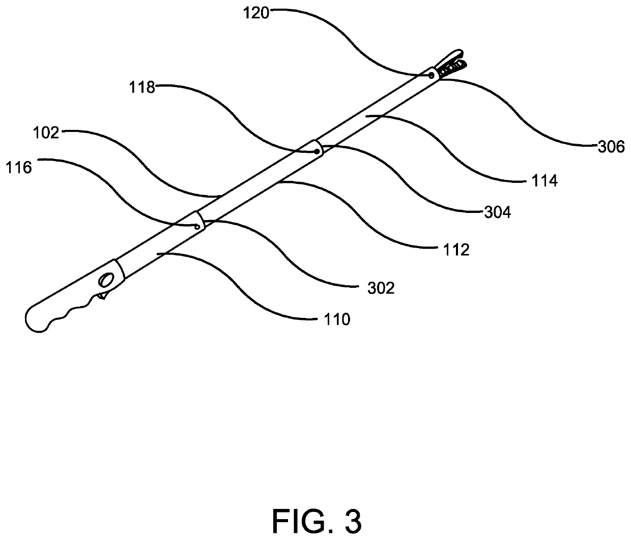
This patent describes a device for safely pulling cables and wires from a ceiling. The device includes a telescoping pole that can be adjusted in length by locking segments. A hook is placed on the wire to be pulled and the device is activated by pressing a mechanical trigger on the grip. This allows the wire to be easily pulled down and moved to different locations. The main advantage of this device is that it eliminates the need for a ladder and provides a convenient solution for installing cables in difficult-to-reach areas of a home or building. The device is also easy to use and can reach up to 18 feet in length with telescoping capabilities.

Problems solved by technology

If the ladder does not meet the required guidelines, the workers' safety is at risk while installing cables using the ladder.
Further, even if the ladder meets safety guidelines, there is always a risk of injury whenever any ladder is involved in a job.
For example, a worker can become imbalanced while climbing a ladder and may accidently fall from the ladder.
This may cause serious injuries to the worker.
Accordingly, when sharing a workspace with others, issues of needing adequate space for a ladder may arise.
Additionally, users may have difficulties with ladder placement in areas that are extremely small and already full of furniture.
Further, use of ladders for cable installation is a time-consuming process, as it requires set up and take down of the ladder which adds additional time to the task.
Due to this, users may find cable installation a time-consuming and tiresome task.
With this, the cable pulling device saves users time.

Method used


Image

  • Telescoping Cable Pulling Device
  • Telescoping Cable Pulling Device
  • Telescoping Cable Pulling Device

Examples


Embodiment Construction

[0027]The innovation is now described with reference to the drawings, wherein like reference numerals are used to refer to like elements throughout. In the following description, for purposes of explanation, numerous specific details are set forth in order to provide a thorough understanding thereof. It may be evident, however, that the innovation can be practiced without these specific details. In other instances, well-known structures and devices are shown in block diagram form in order to facilitate a description thereof. Various embodiments are discussed hereinafter. It should be noted that the figures are described only to facilitate the description of the embodiments. They are not intended as an exhaustive description of the invention and do not limit the scope of the invention. Additionally, an illustrated embodiment need not have all the aspects or advantages shown. Thus, in other embodiments, any of the features described herein from different embodiments may be combined.

[0...


PUM


Abstract

The present invention relates to a telescopic cable and wire-pulling device. The device allows an user to easily pull and install cables in high places, such as a ceiling, without risk of injuries. The cable-pulling device comprises an elongated telescopic pole having a plurality of telescoping segments for adjusting the length of the pole. Each telescoping segment is six feet in length, and can be extended or retracted using slip locks or any other similar telescoping locking mechanism. The device further has a hook on the distal end and a mechanical trigger on the proximal end. The mechanical trigger is depressed to actuate and control the hook for gripping a wire or a cable for pulling down and / or installing the wire or cable at a desired place.

Description

CROSS-REFERENCE TO RELATED APPLICATION[0001]The present application claims priority to, and the benefit of, U.S. Provisional Application No. 63 / 106,570, which was filed on Oct. 28, 2020 and is incorporated herein by reference in its entirety.FIELD OF THE INVENTION[0002]The present invention relates generally to the field of cable installation tools. More specifically, the present invention relates to a telescopic cable-pulling pole with a trigger that allows a cable installer to easily install a cable in a high place, such as a ceiling, without risk of injury. The cable-pulling pole device comprises an elongated telescopic pole having a plurality of telescoping segments for adjusting the length of the pole. The device further comprises a clamping hook on a first end, and a mechanical trigger button on a second end. The second end of the pole device generally comprises a gripping handle that allows the user to properly hold the device while installing a cable. Accordingly, the presen...

Claims


Application Information

Patent Timeline
Patent Type & Authority Applications(United States)
IPC IPC(8): H02G1/08
CPCH02G1/081H02G1/085
Inventor HARRELL, JAMES
Owner HARRELL JAMES
Learn More