Gripper sleeve for urinary catheter
a catheter and sleeve technology, applied in catheters, other medical devices, coatings, etc., can solve the problems of limited dexterity of users of intermittent catheters, easy to slip, and become slippery once removed from the package, so as to reduce discomfort and facilitate use of urinary catheters
- Summary
- Abstract
- Description
- Claims
- Application Information
AI Technical Summary
Benefits of technology
Problems solved by technology
Method used
Image
Examples
second embodiment
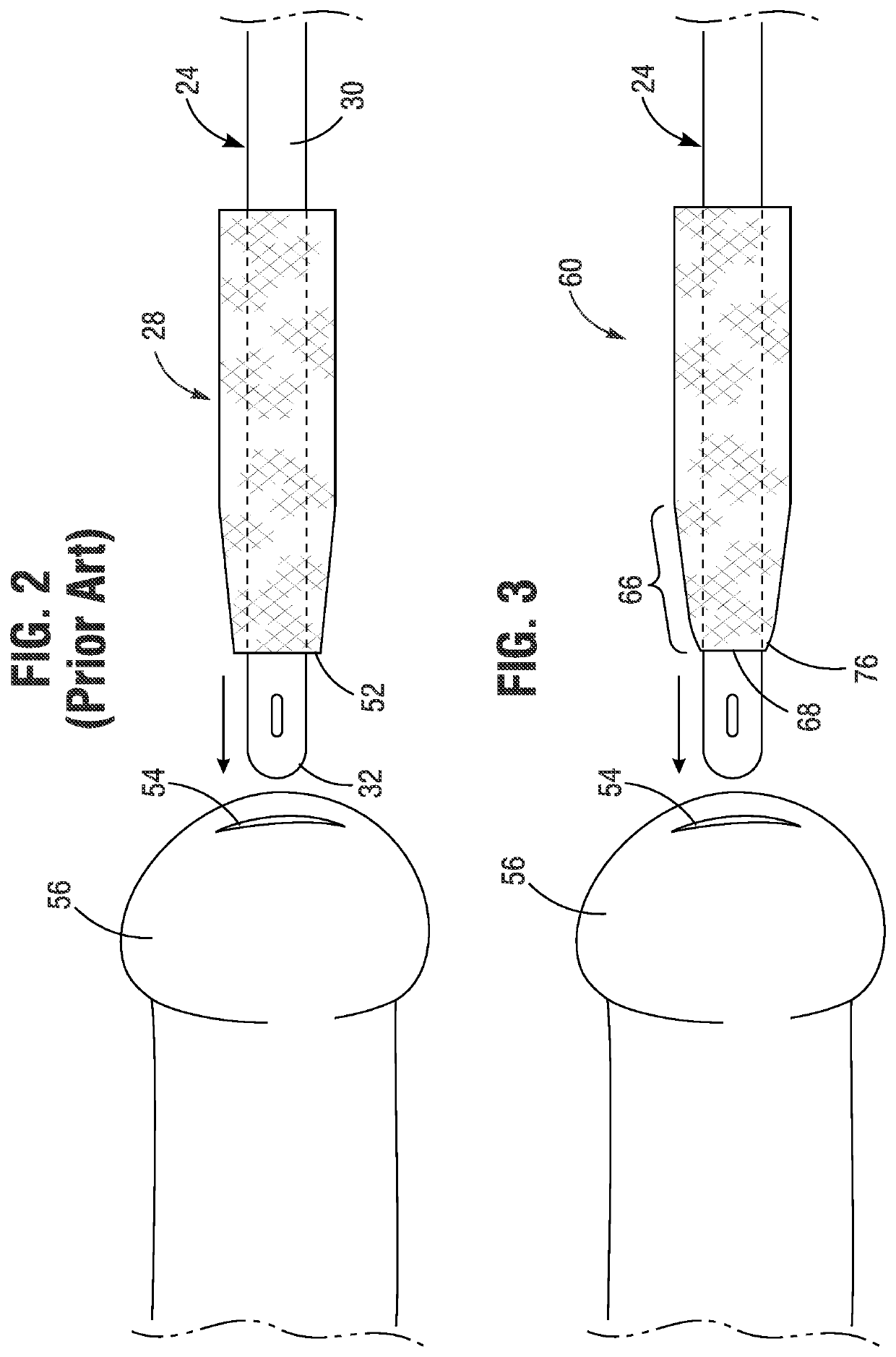
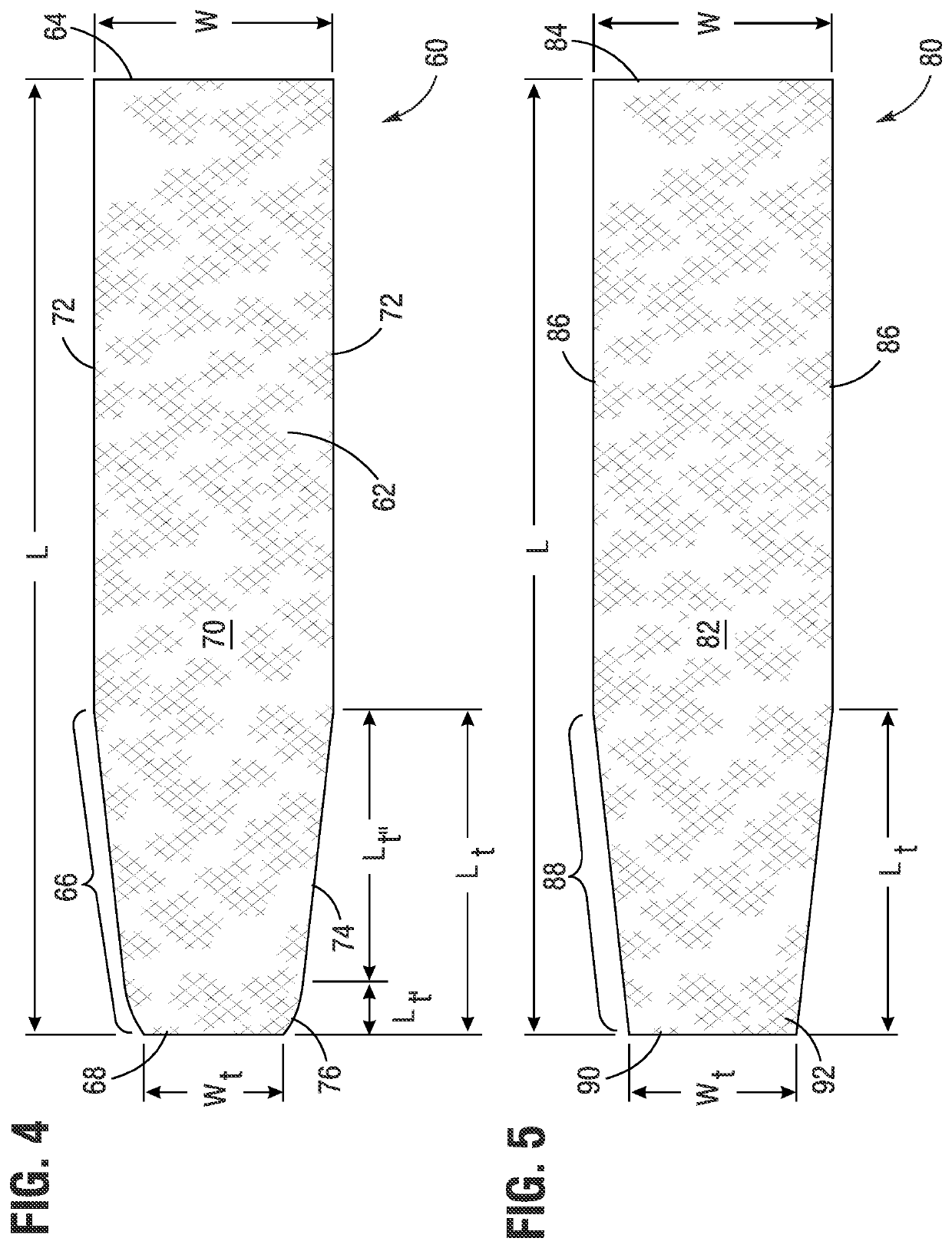
[0043]FIG. 5 is a top plan view of a gripping sleeve 80 of the present application. This gripping sleeve 80 has a shape identical to the prior art gripping sleeve 28, with a proximal portion 82 commencing at a proximal end 84 having sides 86 that are parallel and longitudinally-oriented, and a distal tapered portion 88 terminating at a distal end 90. In this embodiment, the distal tapered portion 88 has a constant narrow taper out to the distal end 90. Although the intersection of the distal tapered portion 88 and the distal end 90 forms sharp corners 92, the two strips of material that comprise the gripping sleeve 80 are only bonded together along the sides 86 in the proximal portion 82, but remain detached in the distal tapered portion 88. It should be noted that the lack of bonding may not be along the whole length of the tapered portion 88 as long as at least about 1-3 mm is detached adjacent the distal end 90.
[0044]This leaves two relatively loose flaps at the distal end 90, wh...
third embodiment
[0045]FIG. 6A is a top plan view of a gripping sleeve 100 of the present application, and FIG. 6B is a perspective view of the gripping sleeve surrounding a urinary catheter 24. Much like the previous gripping sleeve, the gripping sleeve 100 is formed by the attachment of two strips of flexible material connected together in a tubular fashion and have a proximal portion 102 commencing at a proximal end 104 having sides 106 that are parallel and longitudinally-oriented, and a distal tapered portion 108 terminating at a distal end 110. In contrast to the earlier embodiment, the entire distal end 110 is rounded from the end of the tapered portion 108 on either side. This alleviates any discrete corners whatsoever and greatly reduces patient discomfort from inadvertent contact between the sleeve 100 and the area surrounding the urethral opening 54.
[0046]With reference to FIG. 6B, the sleeve 100 is shown near the distal end of the catheter 24. In this version, the distal portion of the s...
fourth embodiment
[0047]FIG. 7A is a top plan view of a gripping sleeve 120 of the present application. As before, the gripping sleeve 120 comprises two strips of flexible material connected together in a tubular fashion to form a proximal portion 122 commencing at a proximal end 124 having sides 126 that are parallel and longitudinally-oriented, and a distal tapered portion 128. In contrast with the earlier embodiment, the two strips of flexible material may not be identical, with a first strip being shorter than a second strip such that a first distal end 130 terminates short of a second distal end 132. Alternatively, the strips could be the same size but offset at each end.
[0048]For instance, the first distal end 130 terminates short of the second distal end 132 by 1-3 mm, preferably 2 mm. In the illustrated embodiment, the first strip is positioned on top of the second strip, though this arrangement could be reversed. The distal tapered portion 128 is shaped similar to that in the gripping sleeve...
PUM
| Property | Measurement | Unit |
|---|---|---|
| included angle | aaaaa | aaaaa |
| length | aaaaa | aaaaa |
| length Lt | aaaaa | aaaaa |
Abstract
Description
Claims
Application Information
 - R&D
- Intellectual Property
- Life Sciences
- Materials
- Tech Scout
- Unparalleled Data Quality
- Higher Quality Content
- 60% Fewer Hallucinations
Browse by: Latest US Patents, China's latest patents, Technical Efficacy Thesaurus, Application Domain, Technology Topic, Popular Technical Reports.
© 2025 PatSnap. All rights reserved.Legal|Privacy policy|Modern Slavery Act Transparency Statement|Sitemap|About US| Contact US: help@patsnap.com


