
Prosthetic cardiac implant

a heart implant and prosthesis technology, applied in the field of medical devices, can solve the problems of svc flow directly colliding with a flat surface, power loss, turbulence, etc., and achieve the effect of reducing the pressure of blood entering the pa and avoiding the svc flow

Pending Publication Date: 2021-11-04
CHANDRASHEKAR CHANDRAMOULI HONNAVALLI
View PDF0 Cites 0 Cited by
  • Summary
  • Abstract
  • Description
  • Claims
  • Application Information

AI Technical Summary

Benefits of technology

This patent describes a device used in heart surgery that allows blood to flow from the inferior vena cava to the pulmonary artery. The device includes a hollow body and a flow separator. The flow separator is designed to guide blood from the inferior vena cava to the right and left pulmonary arteries. The device is used in total cavopulmonary connection surgery, which is a form of heart surgery.

Problems solved by technology

However, such a configuration leads to the SVC flow to directly collide with a flat surface of the insert.
This head on collision results in turbulence, power loss and the like.
Therefore, the insert constricts the path of flow of blood thereby resulting in an undesirable drop in pressure of the blood entering the PA's.
However, the projection of the insert towards the SVC does not bifurcate the flow from SVC rather it is configured to address the problems associated with a small SVC that is not suitable for anastomosis.
Therefore, the placement of an insert inside the framework constricts the path of flow of blood from IVC around the insert thereby resulting in a drop in pressure of blood entering the PA's.
Additionally, the cross shaped external framework results in an increase in the number of suture lines (quadruple anastomosis) and excessive removal of native tissue.
There is no prior art that discloses such an extracardiac connection configuration.

Method used


Image

  • Prosthetic cardiac implant
  • Prosthetic cardiac implant
  • Prosthetic cardiac implant

Examples


Embodiment Construction

[0029]The following detailed description includes references to the accompanying drawings, which form a part of the detailed description. The drawings show illustrations in accordance with example embodiments. These example embodiments, which may be herein also referred to as “examples” are described in enough detail to enable those skilled in the art to practice the present subject matter. However, it may be apparent to one with ordinary skill in the art, that the present invention may be practised without these specific details. In other instances, well-known methods, procedures and components have not been described in detail so as not to unnecessarily obscure aspects of the embodiments. The embodiments can be combined, other embodiments can be utilized, or structural, logical, and design changes can be made without departing from the scope of the claims. The following detailed description is, therefore, not to be taken in a limiting sense, and the scope is defined by the appende...


PUM


Abstract

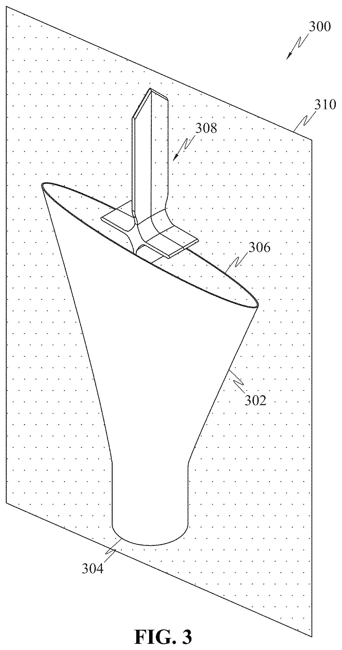
The device (300) for use in total cavopulmonary connection comprises a hollow body (302), embedded within the cavity of which is a flow separator (308). The hollow body (302) comprises a first end (304) that is configured to receive blood from inferior vena cava (IVC) and a second end (306) configured to be connected to pulmonary artery. Further, the flow separator (308) aids in guiding blood from IVC and superior vena cava (SVC) to right pulmonary artery and left pulmonary artery. The flow separator (308) comprises an inferior end (402) and a superior end (404). The inferior end (402) is located between the first end (304) and the second end (306) of the hollow body (302). The flow separator (308) is dimensioned to have the superior end (404) enter SVC when the second end (306) is connected to the pulmonary artery.

Description

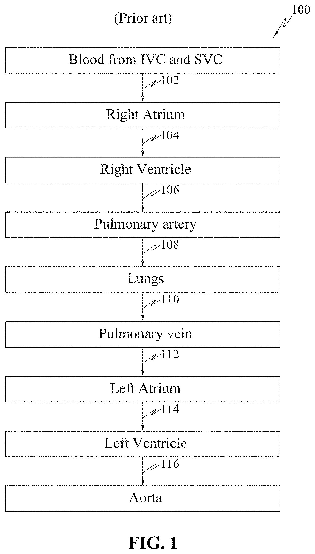
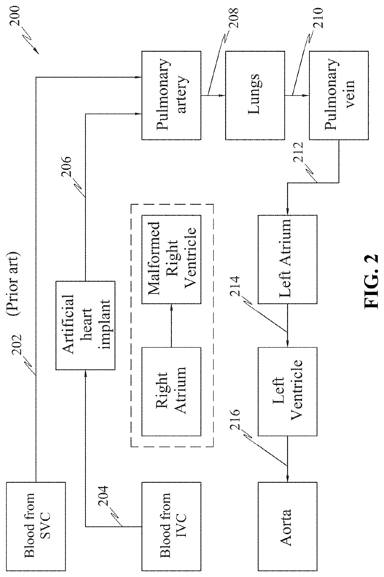
BACKGROUND[0001]Unless otherwise indicated herein, the materials described in this section are not prior art to the claims in this application and are not admitted to being prior art by inclusion in this section.FIELD OF INVENTION[0002]The disclosed subject matter generally relates to the field of medical devices, and more particularly but not exclusively, to the field of artificial heart implants.DISCUSSION OF PRIOR ART[0003]Congenital heart disease (CHD) is defined as a problem in the heart's structure and function that is present at birth. It is reported that CHDs are the leading cause of infant morbidity and mortality. It is estimated that about nine of every 1000 babies born in the United States have a congenital heart disease. It shall be noted that there are more than 35 different known forms of CHDs such as atrial septal defect, ventricular septal defect, hypoplastic left heart syndrome and hypoplastic right heart syndrome, among others. Among all the CHDs, about 20% of them...

Claims


Application Information

Patent Timeline
IPC IPC(8): A61F2/06
CPCA61F2/06A61F2002/061A61F2002/068A61F2250/0039A61F2230/0086A61F2230/0067A61F2220/0075
Inventor CHANDRASHEKAR, CHANDRAMOULI HONNAVALLI
Owner CHANDRASHEKAR CHANDRAMOULI HONNAVALLI
Learn More