Printing device
a printing device and printing technology, applied in printing, typewriters, extruders, etc., can solve the problem of large configuration of the elevating mechanism, and achieve the effect of easy adjustment of the height position of the obj
- Summary
- Abstract
- Description
- Claims
- Application Information
AI Technical Summary
Benefits of technology
Problems solved by technology
Method used
Image
Examples
first embodiment
[0034][1-1. Overall Configuration of Printing Device]
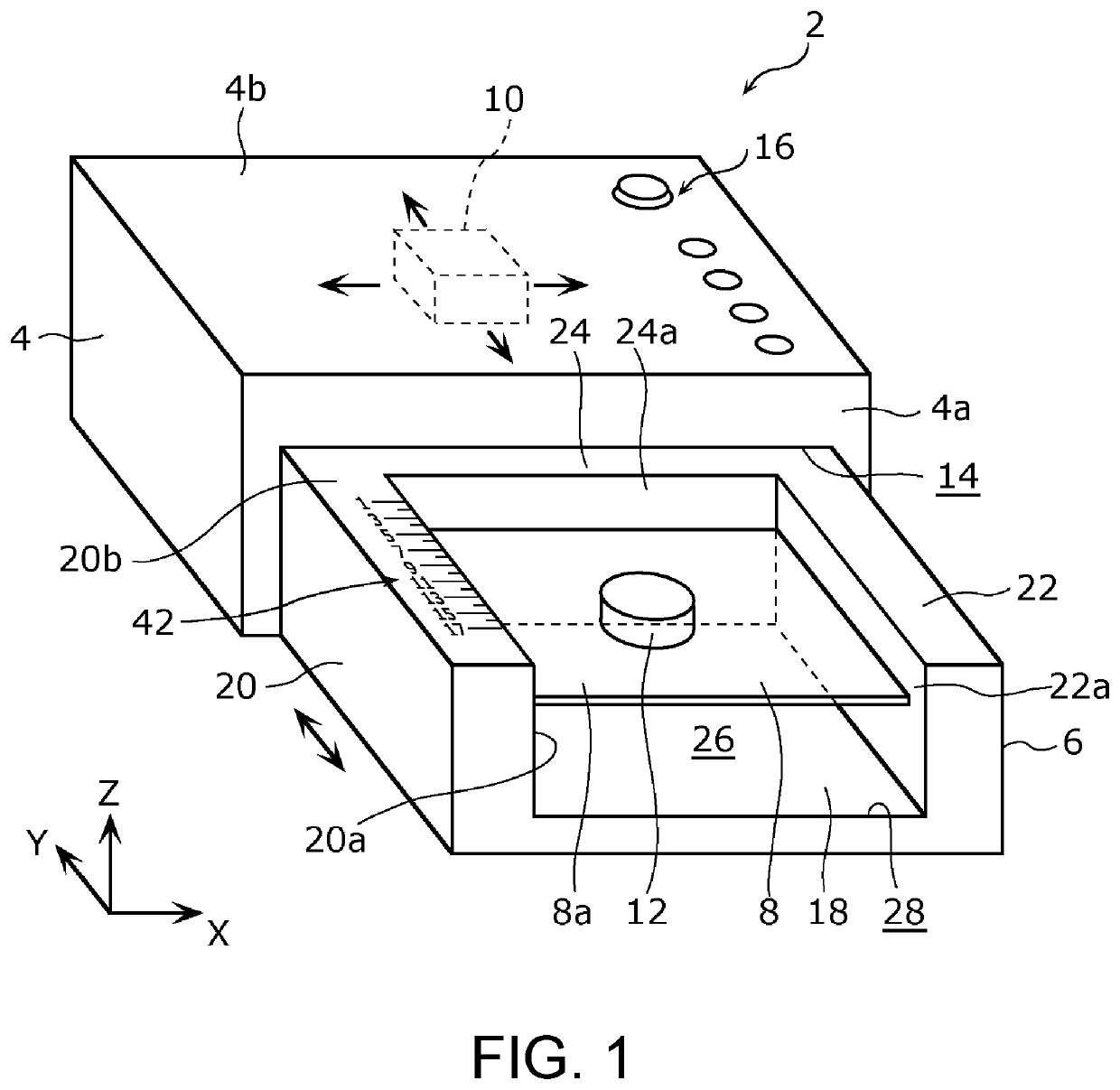
[0035]First, the overall configuration of a printing device 2 according to the first embodiment will be described with reference to FIG. 1. FIG. 1 is a perspective view showing the appearance of the printing device 2 according to the first embodiment. Further, in FIG. 1, the width direction (the left-right direction) of the printing device 2 will be described as the X-axis direction; the depth direction (the front-rear direction) of the printing device 2 will be described as the Y-axis direction; and the height direction (the up-down direction) of the printing device 2 will be described the Z-axis direction.
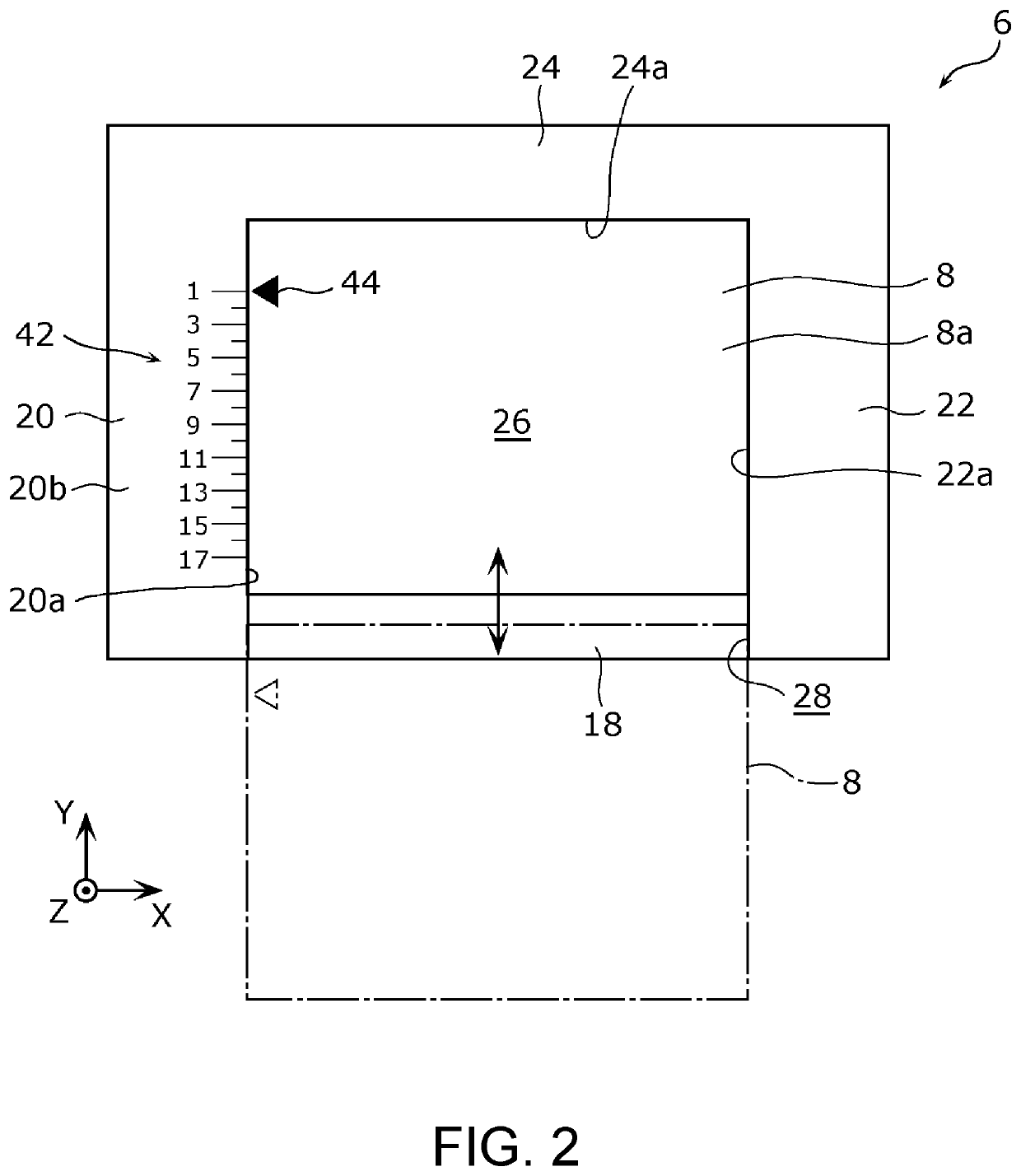
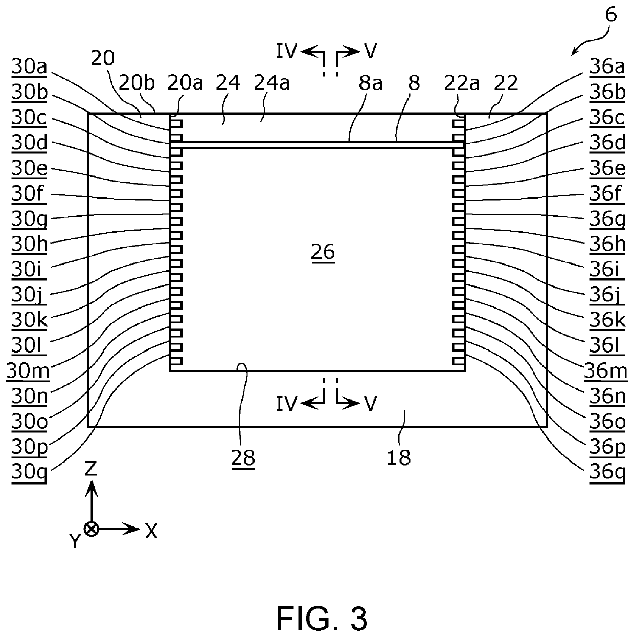
[0036]As shown in FIG. 1, the printing device 2 includes a housing 4, a base part 6, a support member 8, and a head part 10. In the embodiment, the printing device 2 is a what is called food printer for printing a design on an object 12 which is food. In addition, the object 12 is food having various thicknesses, such as a cook...
second embodiment
[2-1. Configuration of Base Part]
[0070]The configuration of a base part 6A according to the second embodiment will be described with reference to FIGS. 9 and 10. FIG. 9 is a top view showing the base part 6A according to the second embodiment in a state where the object 12 is sandwiched between the support member 8 and the third wall 24. FIG. 10 is a side view showing the first wall 20 of the base part 6A according to the second embodiment in a state where the object 12 is placed on the upper surface 8a of the support member 8. Further, in each of the following embodiments, the same components as those of the first embodiment are designated by the same reference numerals, and the description thereof will be omitted.
[0071]As shown in FIG. 9, in the base part 6A according to the second embodiment, the configuration of the third scale 42A is different from that of the first embodiment. Specifically, on the third scale 42A, a plurality of scale lines are displayed along the front-rear d...
third embodiment
[0081][3-1. Configuration of Base Part]
[0082]The configuration of a base part 6B according to the third embodiment will be described with reference to FIGS. 11 and 12. FIG. 11 is a top view showing the base part 6B according to the third embodiment. FIG. 12 is a side view showing the first wall 20 of the base part 6B according to the third embodiment.
[0083]As shown in (a) and (b) of FIG. 11 and FIG. 12, in the base part 6B according to the third embodiment, the configuration of the first scale 34B is different from that of the first embodiment. Specifically, the first scale 34B is provided at the ends of each of the plurality of first slits 30a to 30q on the side of the opening 28.
[0084]For example, for the pair of ridges 32 forming the first slit 30a, the number “1” of the first scale 34B is provided on the upper surface of the lower ridge 32 protruding further to the side of the opening 28 than the upper ridge 32. Similarly, for the pair of ridges 32 forming each of the first slit...
PUM
 Abstract
Description
Claims
Application Information
 - R&D
- Intellectual Property
- Life Sciences
- Materials
- Tech Scout
- Unparalleled Data Quality
- Higher Quality Content
- 60% Fewer Hallucinations
Browse by: Latest US Patents, China's latest patents, Technical Efficacy Thesaurus, Application Domain, Technology Topic, Popular Technical Reports.
© 2025 PatSnap. All rights reserved.Legal|Privacy policy|Modern Slavery Act Transparency Statement|Sitemap|About US| Contact US: help@patsnap.com


