
Machine vision system and method with steerable mirror

Pending Publication Date: 2021-10-21
COGNEX CORP
View PDF8 Cites 2 Cited by
  • Summary
  • Abstract
  • Description
  • Claims
  • Application Information

AI Technical Summary

Benefits of technology

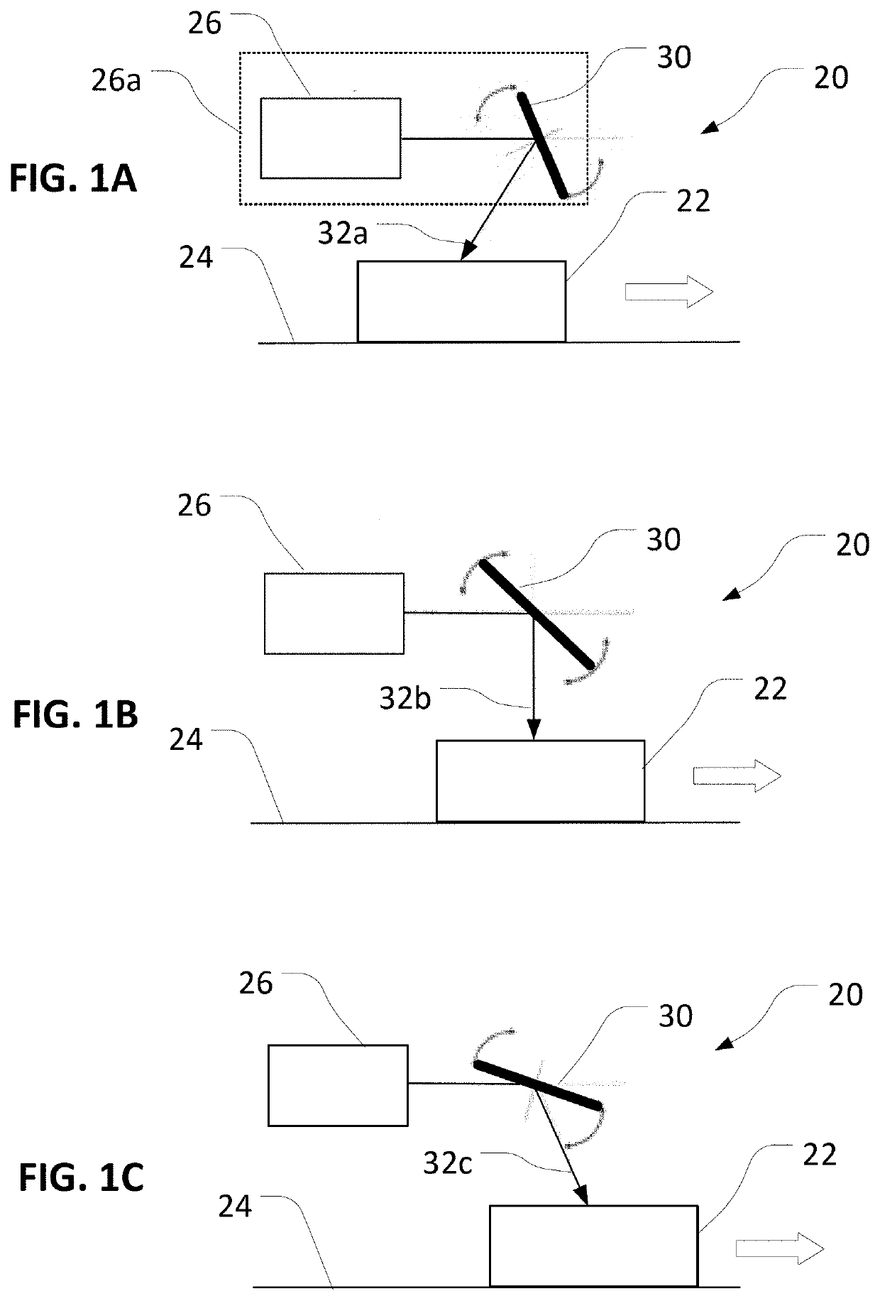
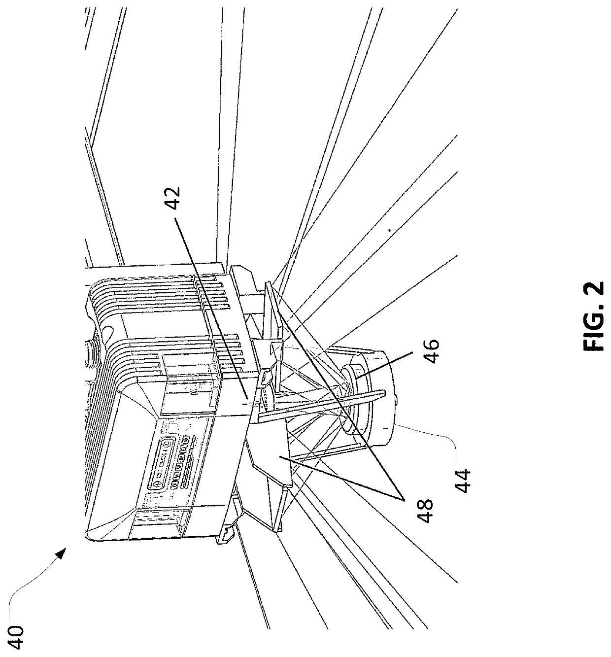
The patent text describes a technology that uses a controllable mirror to change the field of view of a fixed-location imaging device, which can be used to measure the dimensions of objects on a transport system. This technology can provide a more efficient and cost-effective way to acquire images of objects and can be used in various applications such as logistical systems, manufacturing processes, and quality control. The technology can also be used to adjust the field of view to different locations on an object or to provide different degrees of zoom for different objects or locations.

Problems solved by technology

Although conventional approaches can provide useful information, including for identification and decoding of symbols, the installation, calibration, maintenance, and operation of multiple imaging devices may inherently be relatively complex, time consuming, expensive, and subject to error.

Method used


Image

  • Machine vision system and method with steerable mirror
  • Machine vision system and method with steerable mirror
  • Machine vision system and method with steerable mirror

Examples


Embodiment Construction

[0179]The various aspects of the subject technology are now described with reference to the annexed drawings, wherein like reference numerals correspond to similar elements throughout the several views. It should be understood, however, that the drawings and detailed description hereafter relating thereto, including illustration in the drawings of a particular order of operations for a particular method, are not intended to limit the claimed subject matter to the particular form disclosed. Rather, the intention is to cover all modifications, equivalents, and alternatives falling within the spirit and scope of the claimed subject matter.

[0180]In some embodiments, aspects of the disclosure, including computerized implementations of methods according to the disclosure, can be implemented as a system, method, apparatus, or article of manufacture using standard programming or engineering techniques to produce software, firmware, hardware, or any combination thereof to control a processor...


PUM


Abstract

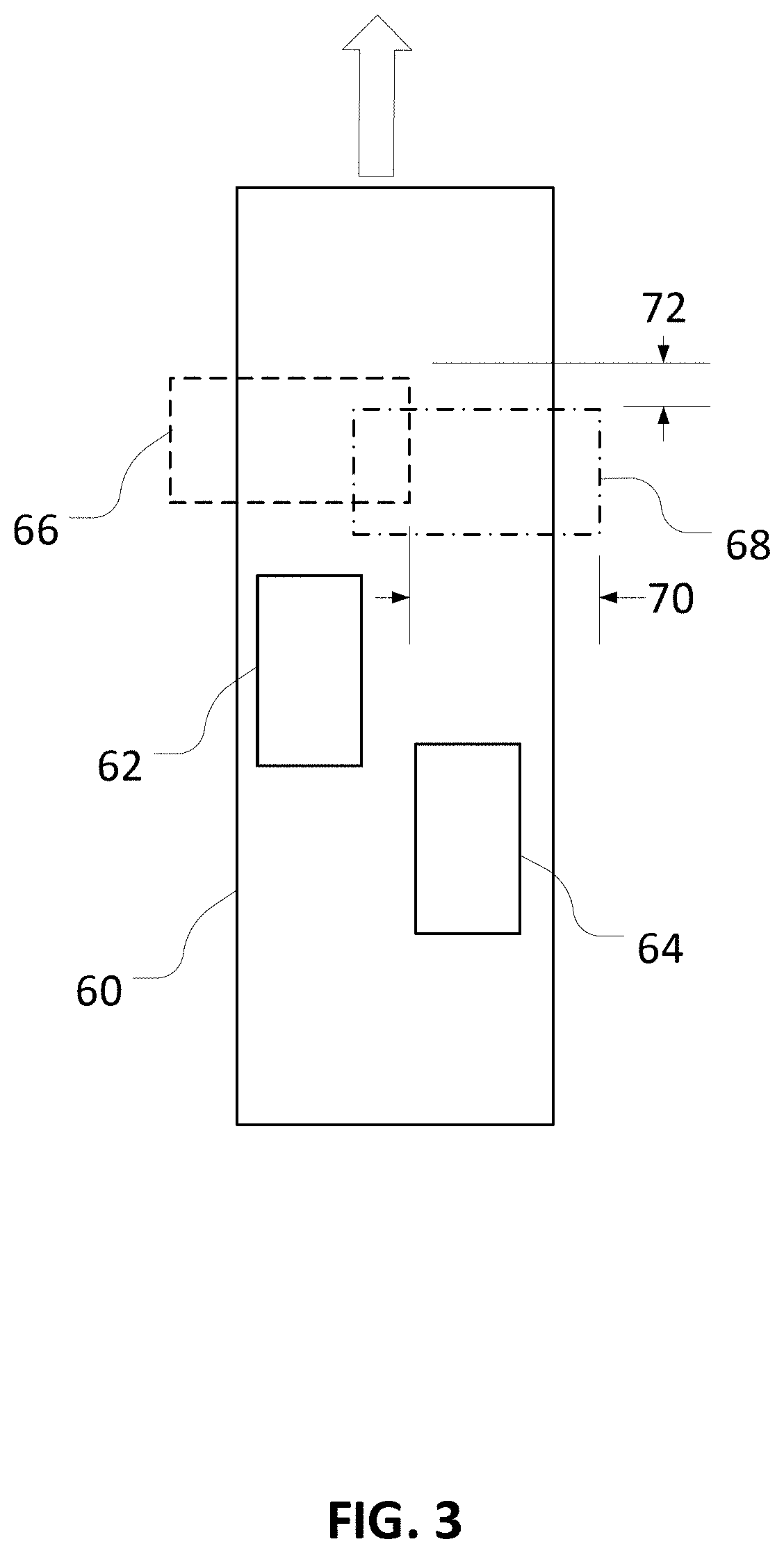
A computer-implemented method for scanning a side of an object to identify a region of interest is provided. The method can include determining, using one or more computing devices, a distance between a side of an object and an imaging device, determining, using the one or more computing devices, a scanning pattern for an imaging device that includes a controllable mirror, based on the distance between the side of the object and the imaging device, moving a controllable mirror according to the scanning pattern to acquire, using the one or more computing device and the imaging device, a plurality of images of the side of the object, and identifying, using the one or more computing devices, the region of interest based on the plurality of images.

Description

CROSS-REFERENCE TO RELATED APPLICATIONS[0001]This application is a continuation in part of U.S. patent application Ser. No. 17 / 071,636 filed Oct. 15, 2020, and entitled, “Machine Vision System and Method with Steerable Mirror,” which is a continuation-in-part of U.S. patent application Ser. No. 16 / 715,078 filed Dec. 16, 2019, and entitled, “Machine Vision System and Method with Steerable Mirror,” both of which are hereby incorporated by reference in their entirety.STATEMENT REGARDING FEDERALLY SPONSORED RESEARCH OR DEVELOPMENT[0002]Not applicable.BACKGROUND OF THE TECHNOLOGY[0003]The present technology relates to imaging systems, including machine vision systems that are configured to acquire and analyze images of objects or symbols (e.g., barcodes).[0004]Machine vision systems are generally configured for use in capturing images of objects or symbols and analyzing the images to identify the objects or decode the symbols. Accordingly, machine vision systems generally include one or ...

Claims


Application Information

Patent Timeline
IPC IPC(8): G06K9/00G06K9/32G05D1/00G05D1/02G02B26/08G06V10/147
CPCG06K9/00791G06K9/3208G06K9/3233G06K2209/21G05D1/0231G02B26/0833G05D1/0094G01S17/89G06V20/52G06V10/147G02B26/10G06V20/56G06V2201/07
Inventor KEMPF, TORSTENRODRIGUEZ, SAUL SANZFERNANDEZ-DORADO, PEPENUNNINK, LAURENS
Owner COGNEX CORP
Learn More