
Wearable camera device

a camera and wearable technology, applied in the field of wearable cameras, can solve the problems of difficult simultaneous solving the requirement of above contradicting structural characteristics, low image resolution, and inability to obtain images from multiple angles, etc., and achieves the effects of convenient manufacture and maintenance, no risk of low-temperature burns, and excellent image quality

Inactive Publication Date: 2021-08-19
LINKFLOW CO LTD
View PDF0 Cites 1 Cited by
  • Summary
  • Abstract
  • Description
  • Claims
  • Application Information

AI Technical Summary

Benefits of technology

The wearable camera device in this patent has several technical benefits. It can be worn for a long time without causing a fire, it is waterproof, and it is easy to manufacture and maintain. The device uses multiple cameras that are stable when worn on the body, and it has a secure power supply line that improves its lifespan. Additionally, the device is comfortable and convenient to assemble. The invention also includes a combining structure that is easy to assemble but stays in place. Overall, this patent provides a high-quality and reliable wearable camera device that improves user convenience and the ability to capture 360-degree images.

Problems solved by technology

However, a conventional wearable camera can capture only images in a specific direction and thus images from multiple angles cannot be obtained or there is a limitation that image resolution is low.
However, in order to capture a 360-degree image in high resolution, a plurality of high-resolution cameras should be mounted on a loop-shaped frame, and in this case, various problems can occur.
However, it is not easy to simultaneously solve the requirement for above contradicting structural characteristics.
However, in order to wear a wearable camera device, the frame should be resiliently deformed, and when this deformation is repeated, damage due to friction, bending, or the like can occur in the power supply line (cable) portion accommodated in the area where the deformation is locally concentrated.
Third, when user wears on a wearable camera for a long time at a scene, heat generated by a high-resolution camera which comes into contact with or is located adjacent to the user's neck can cause low-temperature burns.

Method used


Image

  • Wearable camera device
  • Wearable camera device
  • Wearable camera device

Examples


Embodiment Construction

[0042]Preferable embodiments of the present disclosure will be described with reference to the drawings to sufficiently understand the present disclosure. The embodiments of the present disclosure may be modified into various forms, and the scope of the present disclosure should not be understood as being limited to embodiments which will be described in detail below. Shapes of elements and the like in the drawings may be shown to be exaggerated for clearer descriptions. In the specification, “coupling” or “connection” means not only a case in which two components are directly coupled or connected to each other but also a case in which two components are indirectly coupled or connected to each other with another component. Further, detailed descriptions of known functions and configurations which may unnecessarily obscure the principle of the present disclosure will be omitted.

[0043]Hereinafter, the preferable embodiments of the present disclosure will be described with reference to...


PUM


Abstract

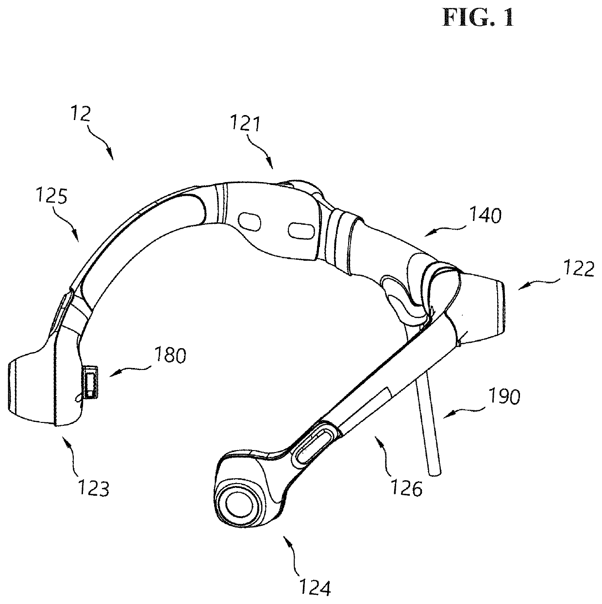
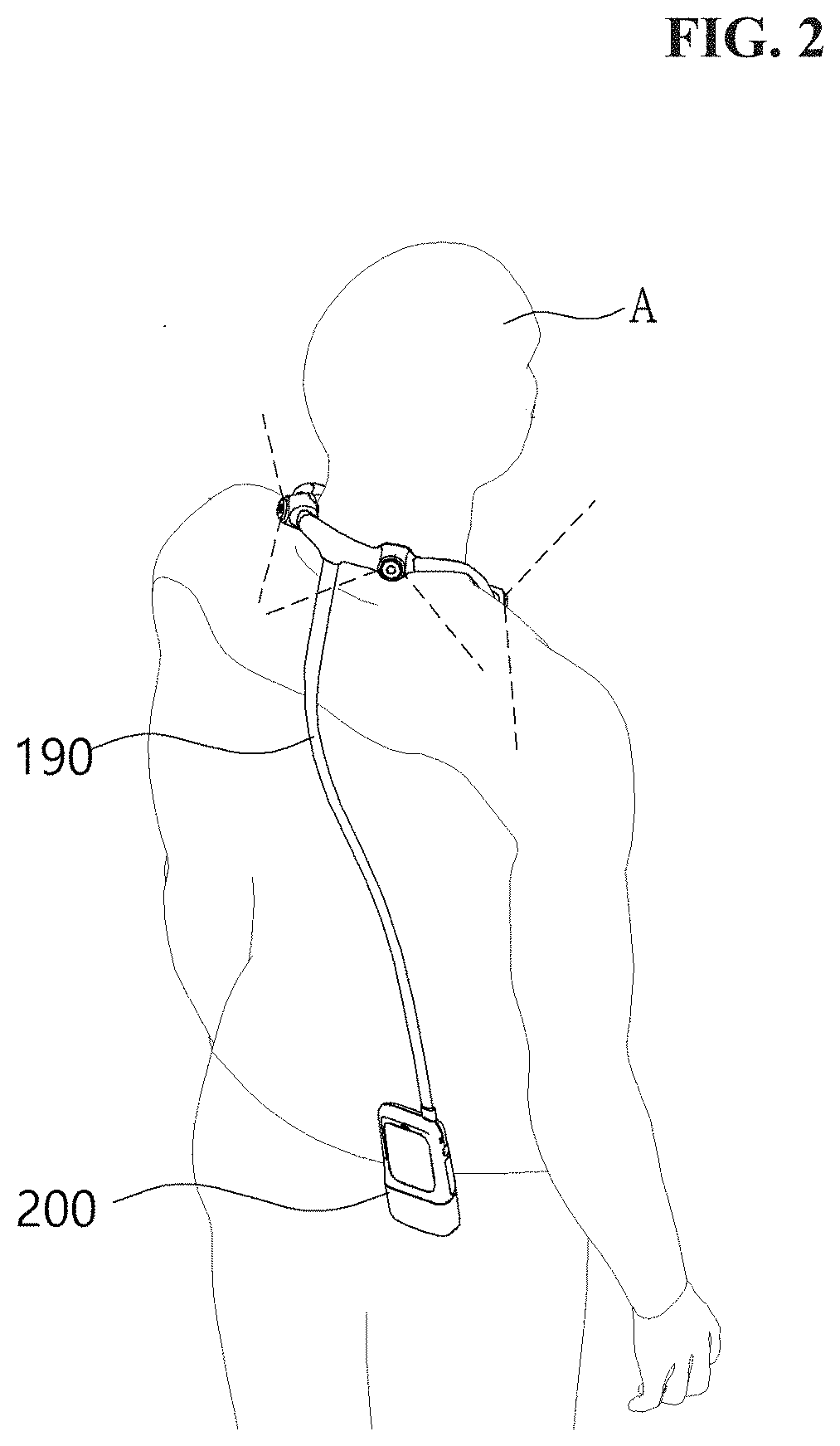
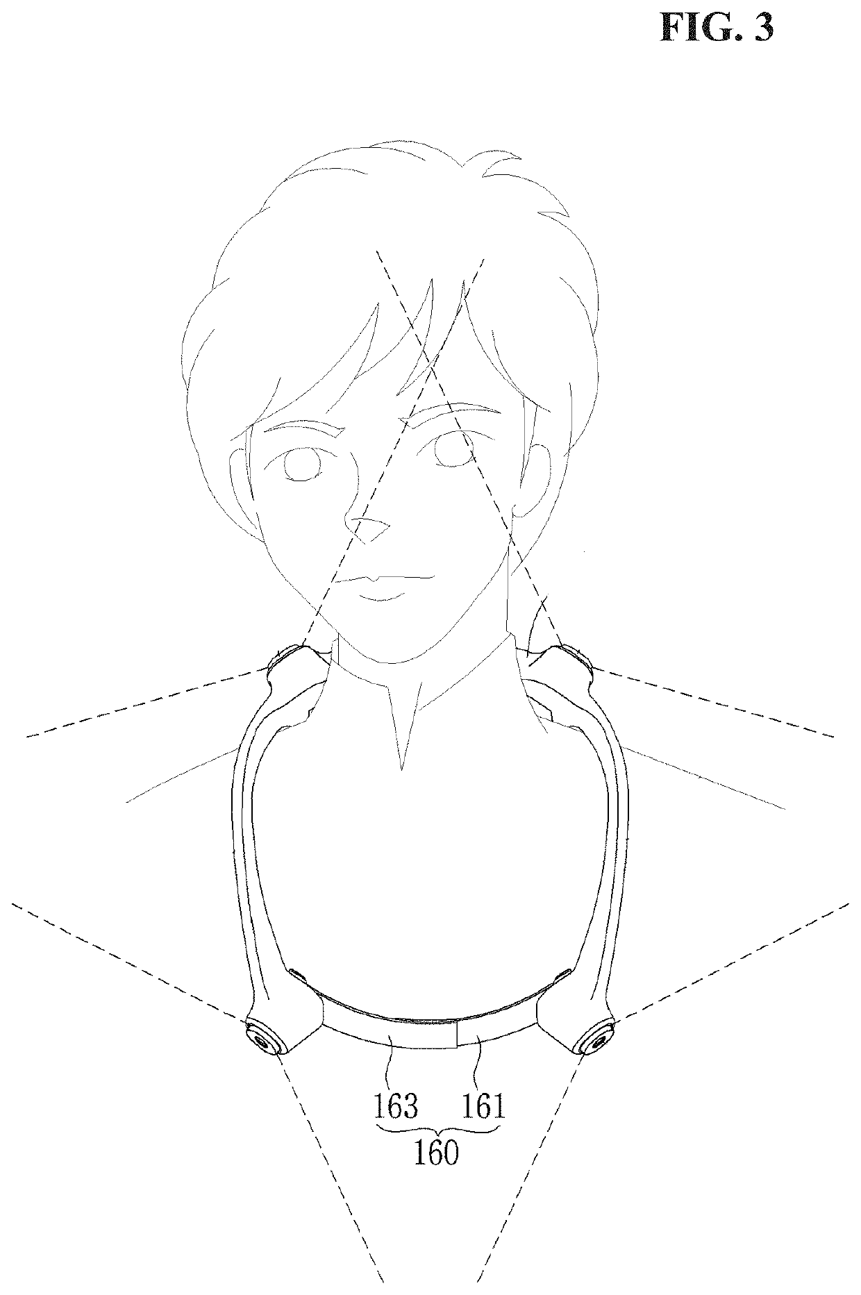
A wearable camera device attachable and detachable to a user's neck includes a central frame. First and second frames are respectively coupled to both sides of the central frame to form a loop-shaped frame part with the central frame. One or more camera modules are provided in the frame part, wherein the first and second frames are outwardly spread and thus the central frame made of an resilient material is resiliently deformed and an open portion at one end of the frame part is generated or expanded to secure a space for wearing the wearable camera device.

Description

TECHNICAL FIELD[0001]The present disclosure relates to a wearable device, and more specifically, to a wearable camera device easily worn on a user's neck and capable of capturing images at various angles simultaneously with enhanced user convenience and safety.BACKGROUND ART[0002]Various wearable devices have been developed and are on the market, and among them, a wearable camera device which is mounted on a user's body to capture the surrounding environment while allowing the user to freely use both hands can be used for various purposes. Specifically, a wearable camera device can be used to capture an immersive video which makes users feel like they are at the scene, or can be used by a police officer or safety officer dispatched to an emergency scene to capture the situation on scene. However, a conventional wearable camera can capture only images in a specific direction and thus images from multiple angles cannot be obtained or there is a limitation that image resolution is low....

Claims


Application Information

Patent Timeline
Patent Type & Authority Applications(United States)
IPC IPC(8): H04N5/225H04N5/232G06F1/16
CPCH04N5/2252G06F1/163H04N5/23219H04N5/2257H04N23/57H04N23/51H04N23/611
Inventor JIN, HONG KYUHWANG, JI HA
Owner LINKFLOW CO LTD
Learn More