
Linear displacement measuring apparatus for determining an absolute position, and linear guide having such a displacement measuring apparatus

a technology of displacement measurement and absolute position, which is applied in the direction of measuring devices, optical conversion of sensor output, instruments, etc., can solve the problems of limiting the choice of the other scale, signal not providing information about a certain absolute position with respect to the material measurement, and the length of rails that are to be manufactured in one piece and are to be suitable for linear guides are usually limited, so as to achieve simple replacement of individual rail segments.

Active Publication Date: 2021-05-13
SCHNEEBERGER HLDG AG
View PDF1 Cites 5 Cited by
  • Summary
  • Abstract
  • Description
  • Claims
  • Application Information

AI Technical Summary

Benefits of technology

The present invention provides a linear displacement measuring device for determining an absolute position with respect to a linear rail composed of multiple rail segments. The device is simple to install and commission, allows for easy replacement of individual rail segments, and allows for a measurement of position changes in the rail at any time. The device uses a scanning device and a pair of sensors to detect position markings on the rail segments and determine the position of the scanning device with respect to the rail. The invention also provides a simplified method for detecting the position of the scanning device by measuring the position difference between the first and second sensors when the scanning device is in a position with respect to the rail. The use of identical rail segments simplifies the installation process and logistics, and allows for a more relaxed assembly order. The technical effects of the invention include improved accuracy and efficiency in position measurement and simplified installation and commissioning of the device.

Problems solved by technology

The lengths of rails that are to be manufactured in one piece and are to be suitable for linear guides are usually limited for manufacturing reasons: With known manufacturing techniques, it is usually only possible to manufacture linear rails with the required precision in one piece, the lengths of which do not exceed a certain upper limit (possibly depending on the respective manufacturing method).
However, this signal does not provide information about a certain absolute position with respect to the material measure.
This displacement measuring device has the disadvantage that all scales must be configured differently in such a manner that each scale differs from all other scales (at least by the respective scale codings).
If one of the scales should become unusable during operation of the measuring system and has to be replaced by another scale, another disadvantage arises from the fact that the unusable scale can only be replaced by another scale which is different from all other scales, thereby limiting the choice of the other scale.
If one of the scales should become unusable during operation of the displacement measuring device and would have to be replaced by another scale, a further disadvantage arises due to the fact that after the unusable scale has been replaced by another scale, an initialization run of the scanning device in the longitudinal direction of the scales (at least over a portion of the scales) must be performed again and the position markings of the respective scales must be repeatedly scanned by means of the scanning device so that after the unusable scale has been replaced, the distances between in each case two adjacent absolute tracks can be re-captured based on updated measured values and stored in the data memory.
The disadvantage of this is that after commissioning of the displacement measuring system, individual plugs can be undesirably removed over time and possibly can be lost, or different plugs may be interchanged or incorrectly placed (e.g. in the wrong place, i.e. not in a hole associated with the respective individual coding formed on the respective plug) by users of the displacement measuring system.
The latter results in errors during the operation of the measuring system when determining a position and consequently impairs the functionality of the measuring system.

Method used


Image

  • Linear displacement measuring apparatus for determining an absolute position, and linear guide having such a displacement measuring apparatus
  • Linear displacement measuring apparatus for determining an absolute position, and linear guide having such a displacement measuring apparatus

Examples


Embodiment Construction

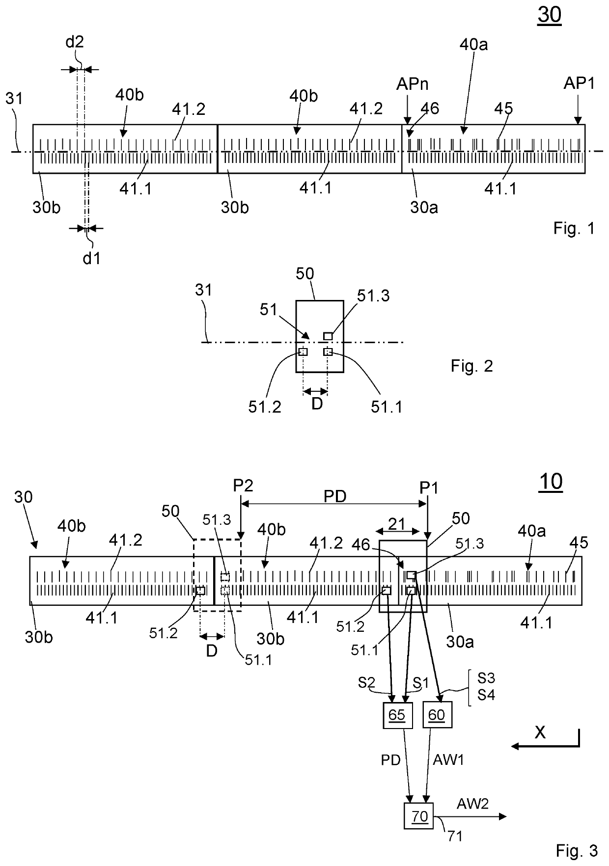
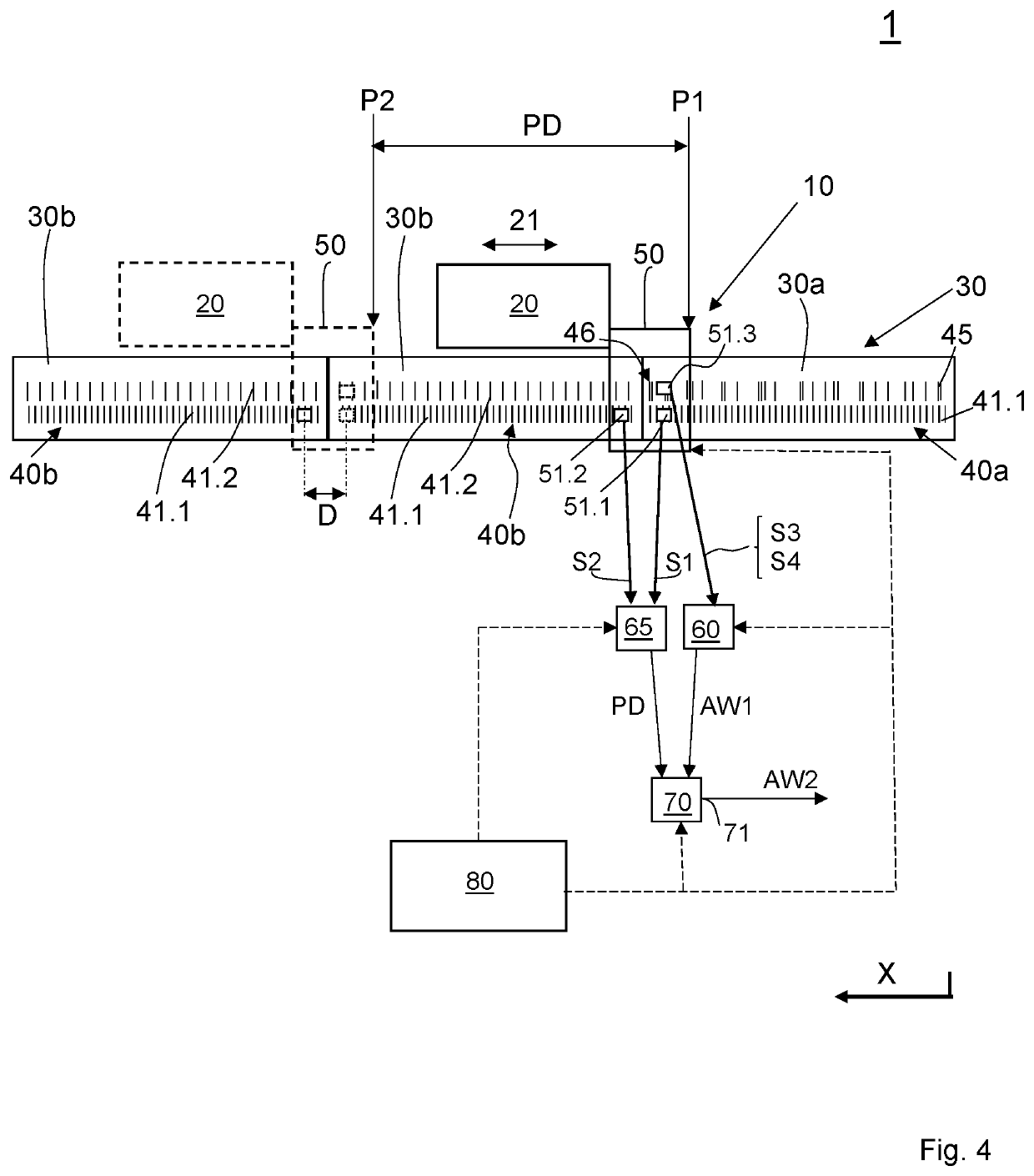
[0046]With reference to FIG. 1-3, the following first explains an embodiment of a linear displacement measuring device according to the invention. FIG. 3 shows—in a schematic representation—an overall view of a linear displacement measuring device 10 according to the invention, which comprises a linear rail 30 composed of a plurality of individual rail segments, and a scanning device 50 movable in the direction of a longitudinal axis 31 of the linear rail 30 for scanning material measures. For clarification of the present facts, FIG. 1 shows a separate schematic illustration of rail 30, and FIG. 2 shows a separate schematic illustration of the scanning device 50.

[0047]As FIGS. 1 and 3 indicate, the rail 30 is composed of two or more individual rail segments, which rail segments are arranged one behind the other in the direction of the longitudinal axis 31, wherein the entirety of all rail segments in the present example has a first rail segment 30a and two second rail segments 30b. ...


PUM


Abstract

A linear displacement measuring apparatus for determining an absolute position includes a linear rail composed of individual rail segments arranged after one another in the direction of a longitudinal axis. Each of the rail segments has a material measure which comprises at least one incremental track which extends along the longitudinal axis and has equidistantly arranged position markings. In addition to the incremental track, the material measure of one of the rail segments has an absolute track with position markings for coding a plurality of absolute positions. A scanning device can be moved along the rail segments and comprises a sensor arrangement for scanning the material measures with a first sensor, a second sensor and a third sensor. The first sensor and the second sensor are offset relative to one another in the direction of the longitudinal axis and are used to detect the position markings of the incremental track.

Description

CROSS-REFERENCE TO RELATED APPLICATIONS[0001]This application claims priority to PCT / CH2018 / 000052 entitled “Linear displacement measuring apparatus for determining an absolute position, and linear guide having such a displacement measuring apparatus” by Klaus-Dieter Götz, published as WO 2019 / 119162, filed on Dec. 19, 2018, which claims priority to German Utility Model DE 202017107880.9 by Klaus-Dieter Götz, filed Dec. 22, 2017, and to Chinese Utility Model CN 201820011057.5 by Klaus-Dieter Götz, filed Jan. 3, 2018. The contents of each of these applications is expressly incorporated herein by reference for all purposes.TECHNICAL FIELD[0002]The invention relates to a linear displacement measuring device for determining an absolute position and a linear guide in combination with a linear displacement measuring device for determining an absolute position.PRIOR ART[0003]Numerous known applications in various technical fields are based on linear guides which are used to guide at least ...

Claims


Application Information

Patent Timeline
Patent Type & Authority Applications(United States)
IPC IPC(8): G01B11/14G01D5/347G01D5/39
CPCG01B11/14G01D5/39G01D5/34753G01D5/2458G01D5/34746G01D5/2454
Inventor GÖTZ, KLAUS-DIETER
Owner SCHNEEBERGER HLDG AG
Learn More