
Integrated conveyor motor

Pending Publication Date: 2021-05-06
NIDEC MOTOR CORP
View PDF0 Cites 3 Cited by
  • Summary
  • Abstract
  • Description
  • Claims
  • Application Information

AI Technical Summary

Benefits of technology

The invention is a conveyor assembly for vehicles that includes a conveyor module, power module, chassis, and tensioning system. The tensioning system includes a tensioning device that is coupled to the conveyor module and selectively shiftable mounted to the chassis. This allows the tension of the conveyor belt to be adjusted by shifting the tensioning system in the fore-aft direction along the chassis. The invention also includes a stiffening assembly that includes a bracket and an insert, which helps improve the stiffness and reduce operational noise of the chassis. Overall, the invention enables efficient and secure adjustment, setting, and maintenance of the conveyor belt tension, and increases the efficiency and safety of the conveyor assembly.

Problems solved by technology

However, conventional conveyor assemblies have various deficiencies.
Among other things, for instance, conveyor assemblies with pulley drives conventionally use tensioning mechanisms that make the conveyor assemblies expensive to manufacture and maintain.

Method used


Image

  • Integrated conveyor motor
  • Integrated conveyor motor
  • Integrated conveyor motor

Examples


first embodiment

Conveyor System—First Embodiment

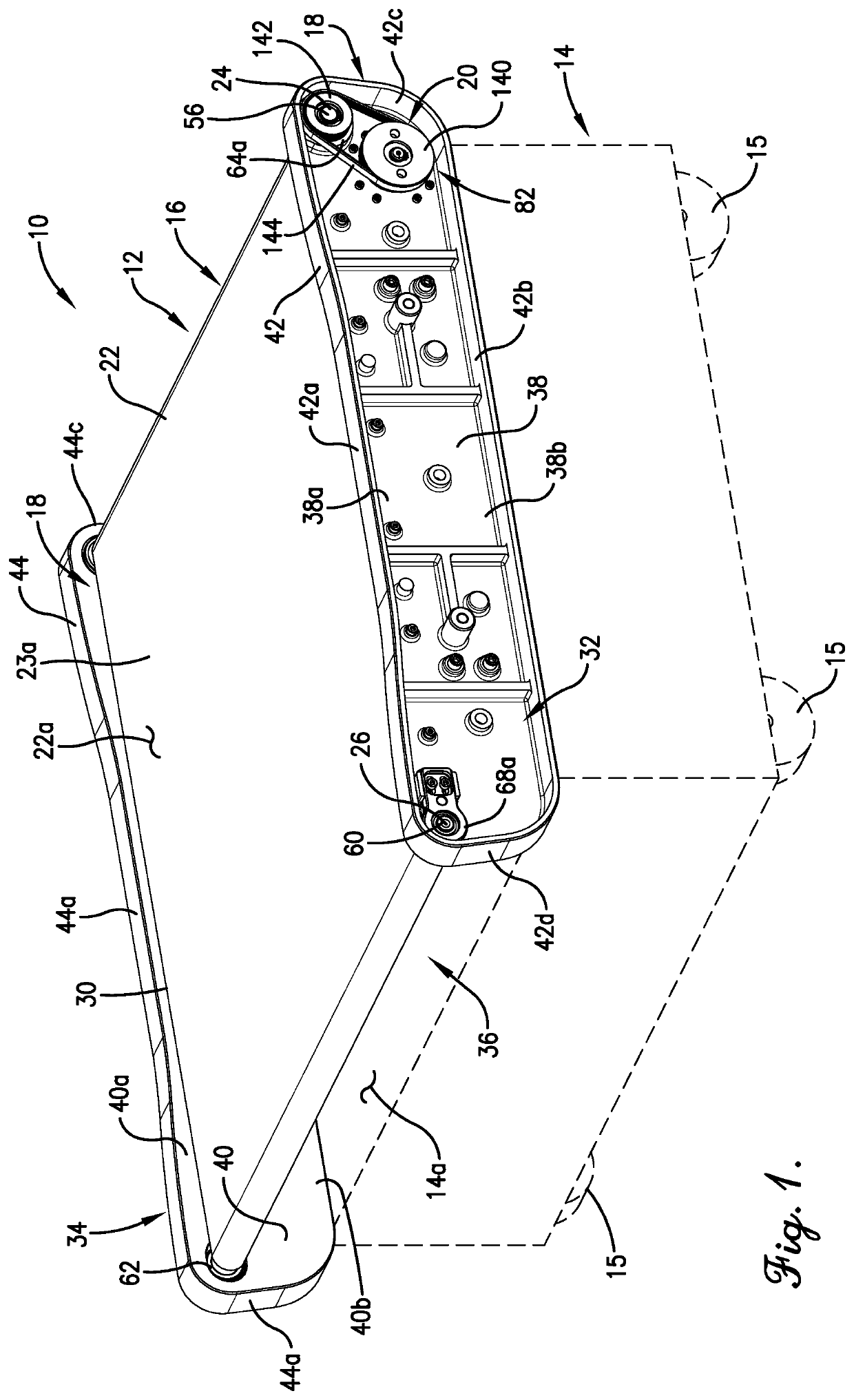
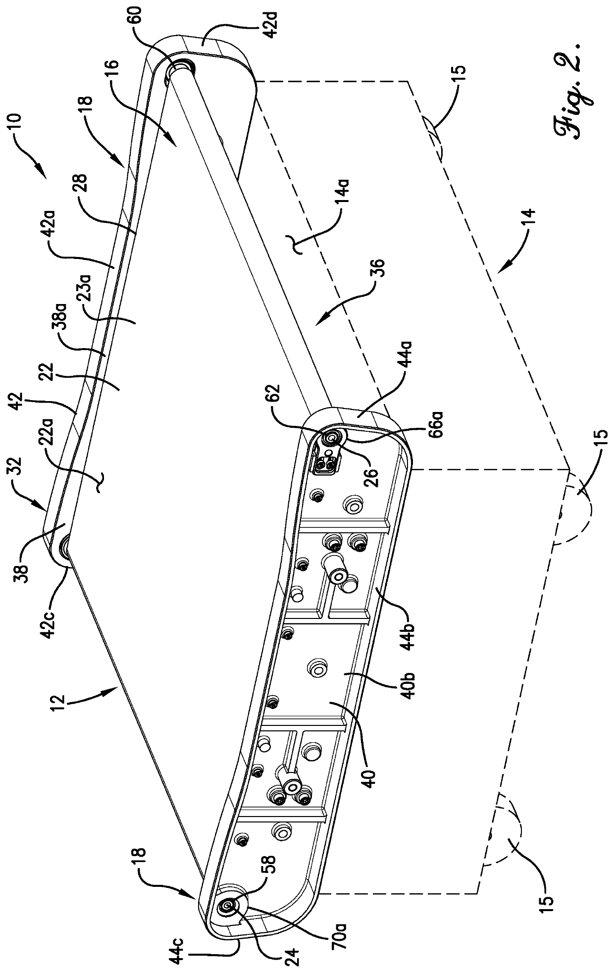
[0036]With initial reference to FIGS. 1 and 2, a mobile conveyor system 10 is provided. The mobile conveyor system 10 preferably comprises a conveyor assembly 12 and a vehicle 14 (shown schematically in hidden line). The conveyor assembly 12 is preferably mounted on and supported by the vehicle 14 in any manner providing suitable stability. More particularly, the conveyor assembly 12 preferably is fixed to a top surface 14a of the vehicle 14.

[0037]The vehicle 14 is preferably moveable to facilitate positioning / repositioning of the conveyor system 10 as a whole and, consequently, of the conveyor assembly 12. In the illustrated embodiment, for instance, the vehicle 14 includes a plurality of wheels 15.

[0038]Most preferably, the vehicle 14 is powered, such that selective movement of the vehicle 14 may be accomplished through use of one or more vehicle motors (not shown) or other power sources. In a preferred embodiment, for instance, each of the wheels 1...

second embodiment

Conveyor System—Second Embodiment

[0096]A second preferred conveyor system is illustrated in FIG. 10. It is initially noted that, with certain exceptions to be discussed in detail below, many of the elements of the conveyor system 210 of the second embodiment are the same as or very similar to those described in detail above in relation to the conveyor system 10 of the first embodiment. Therefore, for the sake of brevity and clarity, redundant descriptions and numbering will be generally avoided here. Unless otherwise specified, the detailed descriptions of the elements presented above with respect to the first embodiment should therefore be understood to apply at least generally to the second embodiment, as well.

[0097]Similarly to the conveyor system 10, the conveyor system 210 of the second preferred embodiment preferably comprises a conveyor assembly 212 and a vehicle 214 (shown schematically in hidden line).

[0098]The vehicle 214 is preferably moveable to facilitate positioning / re...


PUM


Abstract

A conveyor assembly includes a conveyor module including first and second roller bodies and a conveyor belt; a chassis; and a tensioning system. The tensioning system is operable to adjust the tension of the conveyor belt and includes a tensioning device selectively shiftably mounted to the chassis such that shifting of the tensioning system in the fore-aft direction along the chassis results in corresponding fore-aft shifting of the first roller body relative to the second roller body, thereby facilitating adjustment of the tension of the conveyor belt. The chassis includes a pair of side rails and a slider bed. A stiffening assembly includes a bracket spaced vertically below the slider bed such that a vertical gap is formed between the slider bed and the bracket. The stiffening assembly further includes an insert disposed on the bracket and extending upward across at least a portion of the gap.

Description

CROSS-REFERENCE TO RELATED APPLICATION1. Priority Application[0001]The present application is a continuation-in-part of U.S. patent application Ser. No. 16 / 892,959, filed Jun. 4, 2020, which claims the benefit of and priority from U.S. Provisional Patent Application No. 62 / 857,157, filed Jun. 4, 2019, the entire disclosure of each of which is hereby incorporated by reference herein.BACKGROUND OF THE INVENTION1. Field of the Invention[0002]The present invention relates generally to a motor-driven conveyor assembly.2. Discussion of the Prior Art[0003]Conveyor assemblies with motor-driven conveyor belts are often used in the materials handling industry for transport and / or distribution of goods in a workspace such as a commercial warehouse. Some known conveyor systems include a scrolling belt supported by a pair of rollers, with one of the rollers being rotatably powered by a motor via indirect attachment thereto (e.g., via a transmission such as a pulley drive).[0004]However, conventi...

Claims


Application Information

Patent Timeline
IPC IPC(8): B65G23/44B65G21/22B65G21/14
CPCB65G23/44B65G21/22B65G2812/02069B65G2812/02148B65G2812/02168B65G21/14F16C13/02F16C19/54F16C2326/58B65G23/22B65G41/008B65G2207/28B65G23/08
Inventor BIRO, JOSHUA M.MOORE, WILLIAM D.FADLER, RICHARD J.
Owner NIDEC MOTOR CORP
Learn More