
Painting system

a painting system and painting technology, applied in the field of painting systems, can solve the problems of increasing the size of the entire painting system, reducing the temperature of the painting zone, and difficulty in achieving good painting quality in the second painting zone, so as to avoid degradation of painting quality and reduce the size of the entire system

Inactive Publication Date: 2021-04-01
TOYOTA JIDOSHA KK
View PDF0 Cites 1 Cited by
  • Summary
  • Abstract
  • Description
  • Claims
  • Application Information

AI Technical Summary

Benefits of technology

The present disclosure aims to provide a painting system that can be smaller in size. The painting zones are connected in series by a cascade air passage, allowing air to flow through the painting zones. A dry mist remover is used to remove paint mist in the air that has passed through the painting chamber of each painting zone. A feedback control is performed on the temperature and humidity of air in one painting zone to adjust it and avoid degradation of painting quality. This allows for appropriate adjustment in each painting zone without providing a recycling air conditioner on the route of the air flow passage.

Problems solved by technology

In the painting system of JP 2016-67998 A, air having undergone changes in the temperature and the humidity while passing through the first painting zone is supplied as is to the second painting zone, but the temperature and the humidity of the second painting zone are given no consideration, which makes it difficult to achieve good painting quality in the second painting zone.
However, such a recycling air conditioner would inevitably add to the size of the entire painting system.
Moreover, supplying the conditioned air to the painting zone under the feedback control can decrease the temperature of this painting zone.

Method used


Image

  • Painting system
  • Painting system
  • Painting system

Examples


first embodiment

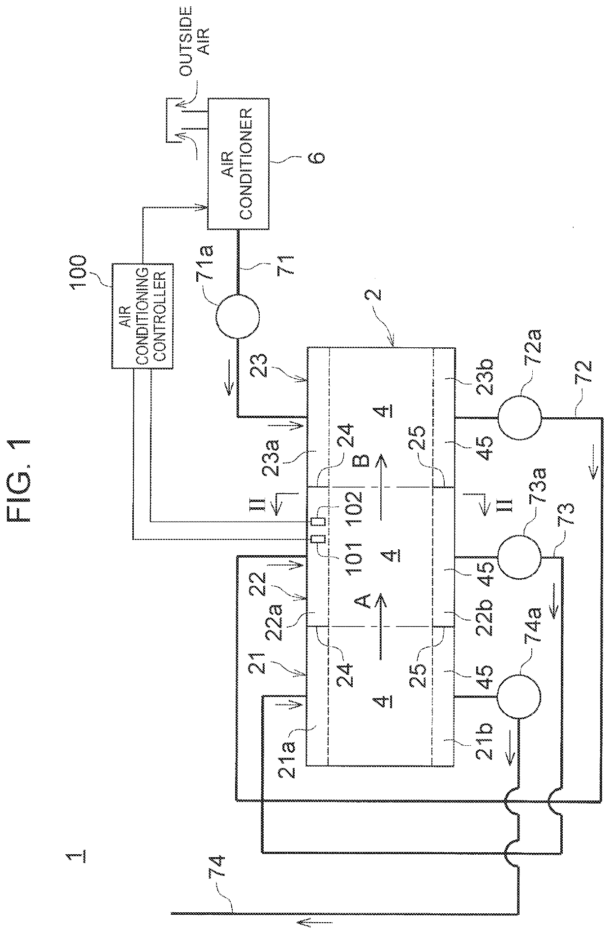
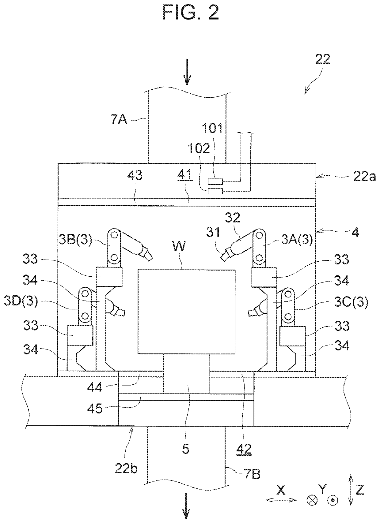
[0031]FIG. 1 is a diagram showing a schematic configuration of a painting system 1 according to a first embodiment. As shown in FIG. 1, a painting booth 2 of the painting system 1 according to this embodiment has three painting zones 21, 22, 23. A body W (see FIG. 2) of an automobile that is an object-to-be-painted is painted while being transferred sequentially through the three painting zones 21, 22, 23 (see arrows A and B in FIG. 1).

[0032]Specifically, in FIG. 1, the painting zone located on the leftmost side is a first painting zone 21; the painting zone located at the center is a second painting zone 22; and the painting zone located on the rightmost side is a third painting zone (the “fresh air-introduced painting zone” as termed in the present disclosure) 23.

[0033]The first painting zone 21 is a painting zone in which inner surfaces of doors (not shown) of the body W are painted. The second painting zone 22 is a painting zone in which exterior panels (exterior panels of the d...

second embodiment

[0069]Next, a second embodiment will be described. This embodiment is different from the first embodiment in the configuration of the air flow passage. The other configurations and the actions in the painting process in this embodiment are the same as those in the first embodiment, and therefore only differences from the first embodiment in the configuration of the air flow passage and the airflow during the painting process will be described here.

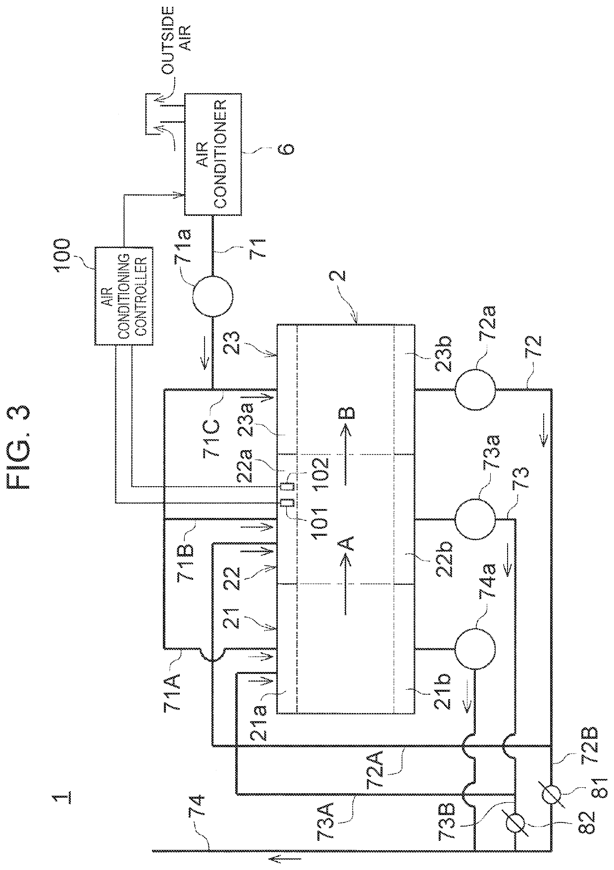
[0070]FIG. 3 is a diagram showing a schematic configuration of the painting system 1 according to this embodiment. Those members of FIG. 3 that are the same as the constituent members of the painting system 1 described in the first embodiment and shown in FIG. 1 will be denoted by the same reference signs and the description thereof will be omitted.

[0071]As shown in FIG. 3, in the painting system 1 according to this embodiment, a downstream-side part of the air supply duct 71 is branched into a first air supply duct 71A, a second air suppl...

third embodiment

[0081]Next, a third embodiment will be described. This embodiment is different from the second embodiment in the configuration of the air flow passage and the control over the airflow. The other configurations and the actions in the painting process in this embodiment are the same as those in the above embodiments, and therefore only differences from the above embodiments in the configuration of the air flow passage and the control over the airflow will be described here.

[0082]FIG. 4 is a diagram showing a schematic configuration of the painting system 1 according to this embodiment. Those members in FIG. 4 that are the same as the constituent members of the painting system 1 described in the above embodiments and shown in FIG. 1 and FIG. 3 will be denoted by the same reference signs and the description thereof will be omitted.

[0083]As shown in FIG. 4, the first air supply duct 71A is provided with a third air conditioning damper 83 of which the opening degree is adjustable, and the...


PUM


Abstract

A plurality of painting zones is connected in series by a plurality of air exhaust ducts so as to allow air to flow through the painting zones. A paint mist in air having passed through a painting chamber of each painting zone is removed by a dry filter. Feedback control is performed on the temperature and the humidity of air in a second painting zone other than a third painting zone to which conditioned air from an air conditioner is supplied. Thus, it is possible to appropriately adjust the temperature and the humidity of each painting zone and avoid degradation of painting quality in each painting zone, while achieving downsizing of the entire system by not providing a recycling air conditioner on the route of an air flow passage.

Description

INCORPORATION BY REFERENCE[0001]The disclosure of Japanese Patent Application No. 2019-176734 filed on Sep. 27, 2019 including the specification, drawings and abstract is incorporated herein by reference in its entirety.BACKGROUND1. Technical Field[0002]The present disclosure relates to a painting system that paints objects-to-be-painted, for example, the bodies of automobiles. More particularly, the present disclosure relates to improvement of a painting system that includes a plurality of painting zones and paints an object-to-be-painted in each painting zone.2. Description of Related Art[0003]A painting system disclosed in Japanese Patent Application Publication No. 2016-67998 (JP 2016-67998 A) is conventionally known as a painting system that paints objects-to-be-painted, such as the bodies of automobiles, by spraying a mist of paint onto the objects-to-be-painted. In the painting system of JP 2016-67998 A, a painting booth in which objects-to-be-painted are painted is divided i...

Claims


Application Information

Patent Timeline
IPC IPC(8): B05B16/60B05B16/00B05B14/43F24F11/30
CPCB05B16/60B05B16/90F24F2110/10F24F11/30B05B14/43B05B16/20B05B14/40B05B13/0431Y02P70/10
Inventor FUJIWARA, KEIICHITANI, SHINJINUMASATO, AKIRATANAKA, KAZUKI
Owner TOYOTA JIDOSHA KK
Learn More