Keyswitch structure
- Summary
- Abstract
- Description
- Claims
- Application Information
AI Technical Summary
Benefits of technology
Problems solved by technology
Method used
Image
Examples
Example
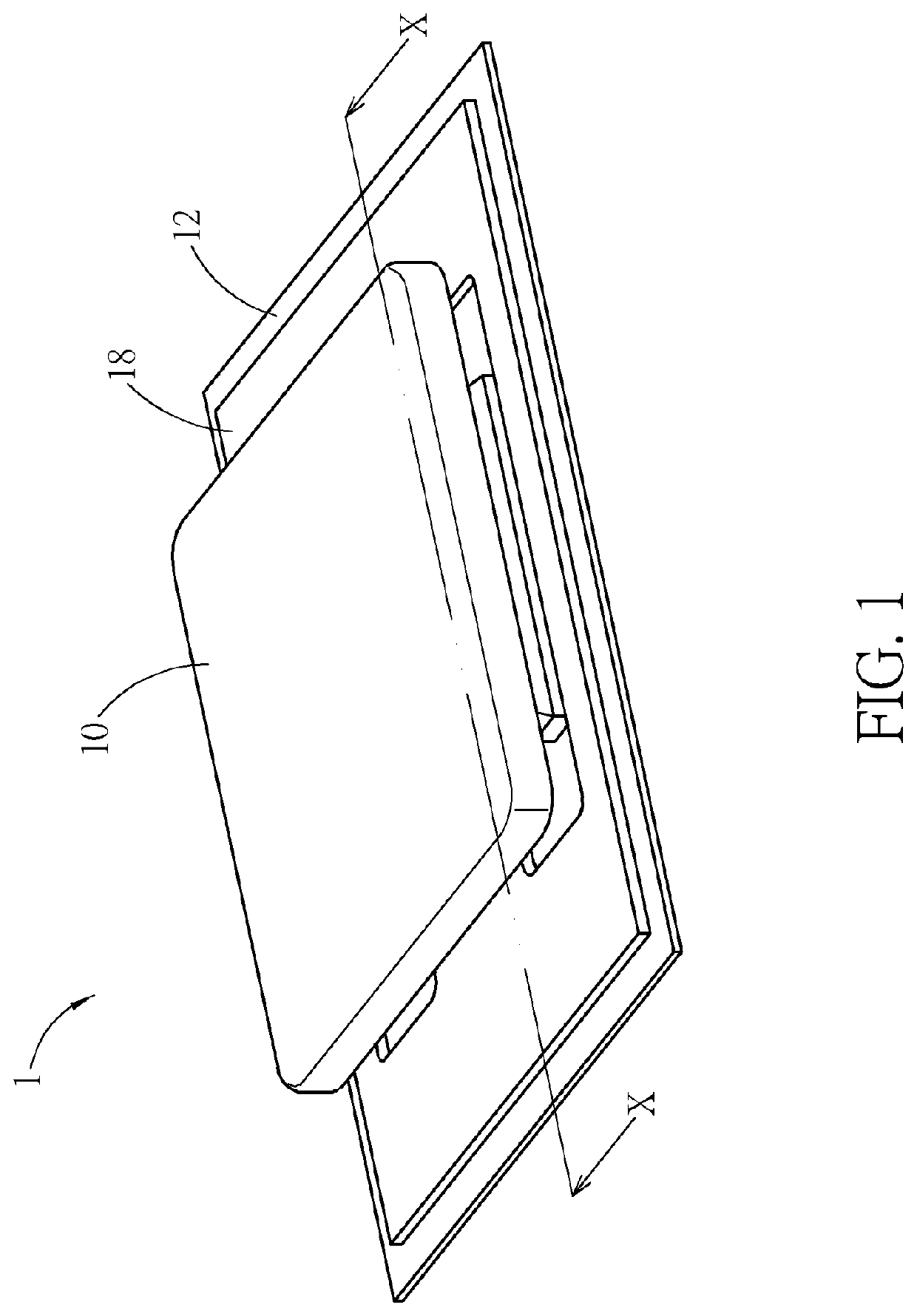
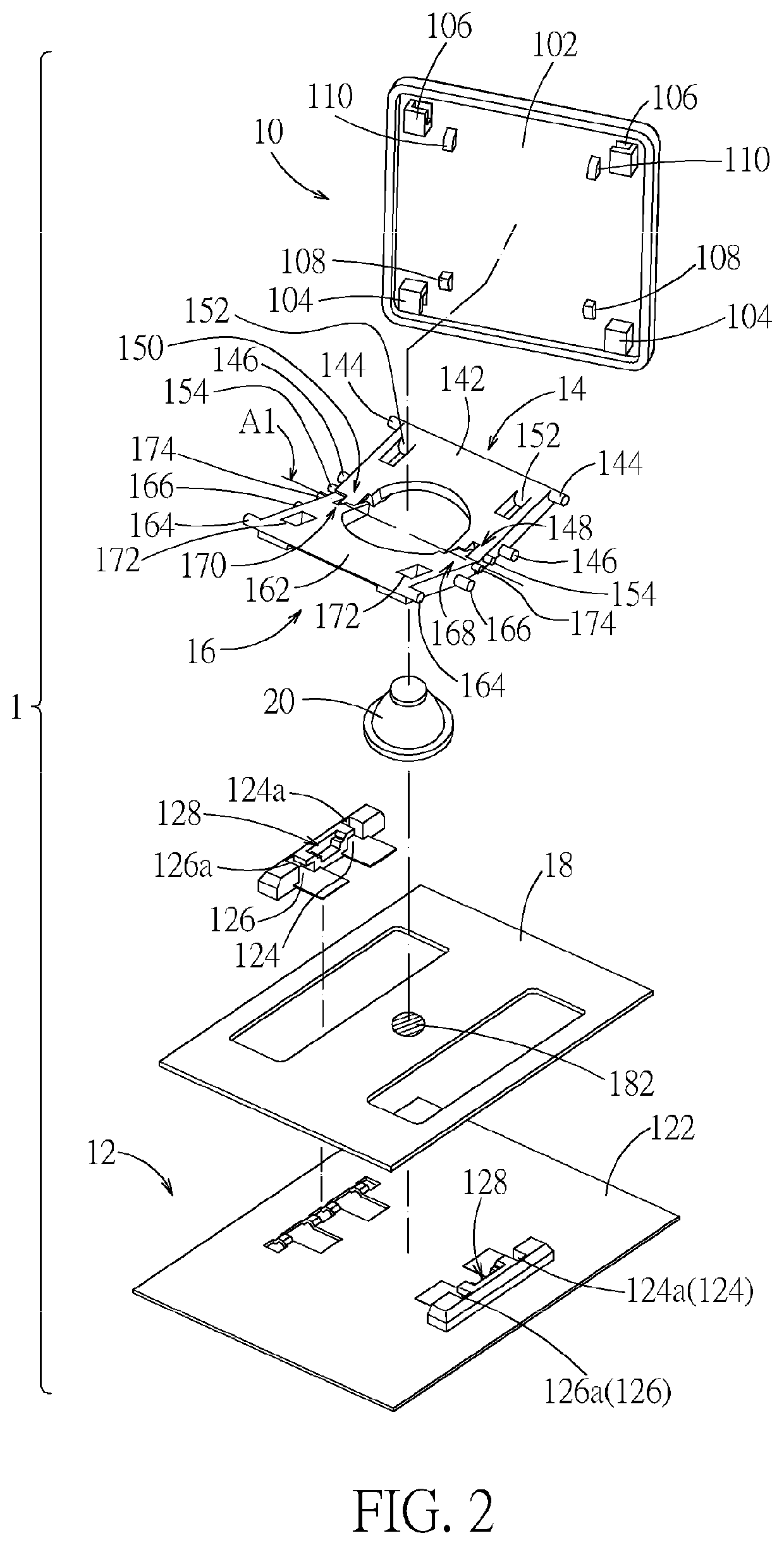
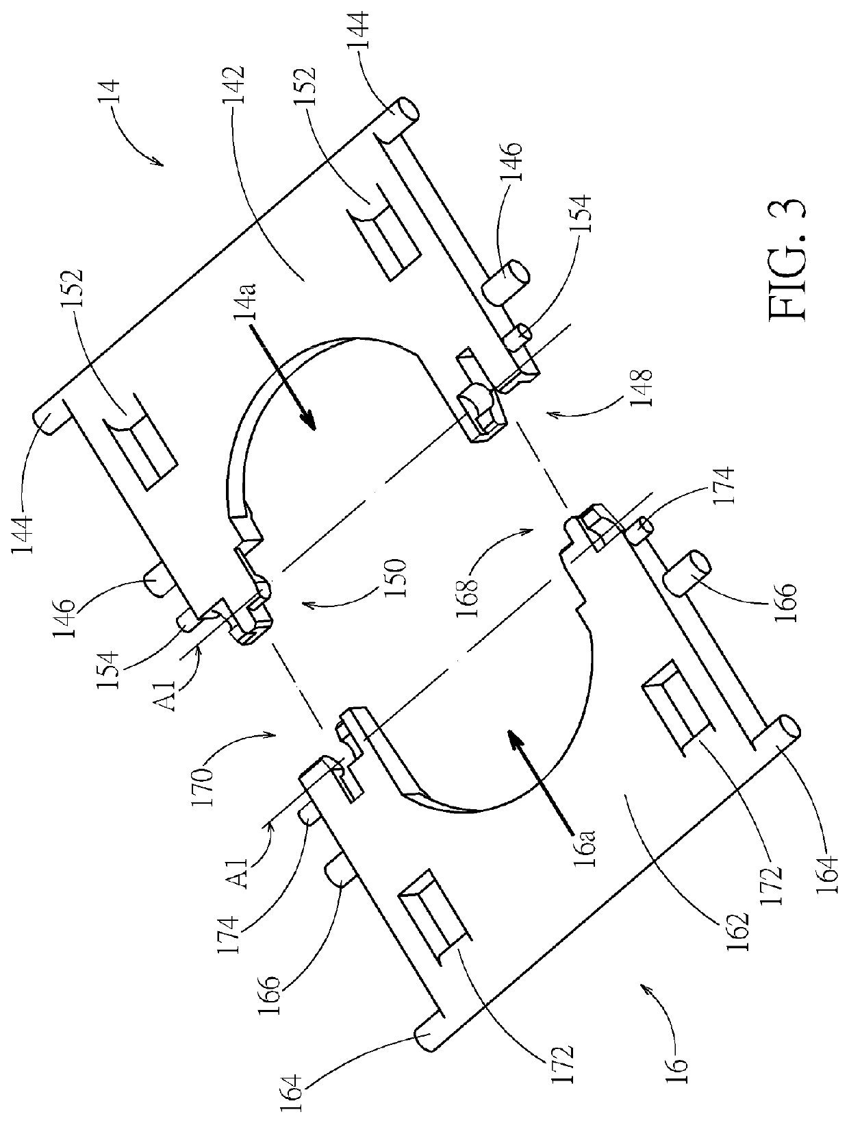
[0033]Please refer to FIG. 1 and FIG. 2. A keyswitch structure 1 according to embodiment includes a keycap 10, a base 12, a first support 14, a second support 16, a switch circuit board 18, and a resilient restoration part 20. The base 12 is disposed under the keycap 10. The first support 14 and the second support 16 are pivotally connected relative to a rotation axis A1 (indicated by a chain line in FIG. 2) and respectively connected to and between the keycap 10 and the base 12. The switch circuit board 18 is placed on the base 12. The resilient restoration part 20 is placed on the switch circuit board 18 corresponding to a switch 182 (indicated by a circle with dashed lines in FIG. 2) of the switch circuit board 18. The keycap 10 can move up and down relative to the base 12 through the first support 14 and the second support 16. When moving down, the keycap 10 can press the resilient restoration part 20 to trigger the switch 182. In practice, the switch circuit board 18 can be but...
PUM
 Abstract
Description
Claims
Application Information
 - R&D
- Intellectual Property
- Life Sciences
- Materials
- Tech Scout
- Unparalleled Data Quality
- Higher Quality Content
- 60% Fewer Hallucinations
Browse by: Latest US Patents, China's latest patents, Technical Efficacy Thesaurus, Application Domain, Technology Topic, Popular Technical Reports.
© 2025 PatSnap. All rights reserved.Legal|Privacy policy|Modern Slavery Act Transparency Statement|Sitemap|About US| Contact US: help@patsnap.com


