
Wireless charging systems and methods for increasing power transfer functions

a technology of wireless charging and power transfer function, which is applied in the direction of exclusive-or-circuits, instruments, transportation and packaging, etc., can solve the problems of poor battery life and defeat the purpose of wireless technology in general

Active Publication Date: 2020-12-31
LOGITECH EURO SA
View PDF0 Cites 6 Cited by
  • Summary
  • Abstract
  • Description
  • Claims
  • Application Information

AI Technical Summary

Benefits of technology

The patent describes a wireless charging system that includes a charging device and a computer accessory device. The charging device has a processor and a receiver coil, while the computer accessory device has a power receiving circuitry. The charging device generates a magnetic field and receives power from a power source. The power receiving circuitry measures the power and a power tracking controller generates a control signal to modify the output impedance of an amplifier, resulting in a different power output. The system uses a resonator circuity to generate the magnetic field and can adjust the power output to provide wireless power to the computer accessory device. The technical effect of this system is to provide a more efficient and flexible way to charge computer accessories wirelessly.

Problems solved by technology

Wireless peripheral devices (e.g., computer mice, keyboards, speakers, ear buds, smart wearables, etc.) are widely used and provide portability and convenience, but often suffer from poor battery life.
Although battery technology continues to improve, most peripheral devices require a charging cable for extended usage, which can be cumbersome, limiting, and defeat the purpose of wireless technology in general.

Method used


Image

  • Wireless charging systems and methods for increasing power transfer functions
  • Wireless charging systems and methods for increasing power transfer functions
  • Wireless charging systems and methods for increasing power transfer functions

Examples


Embodiment Construction

[0018]The present disclosure relates in general to input devices, and in particular to the wireless charging of input devices.

[0019]In the following description, various embodiments of methods and systems for wirelessly charging an input device will be described. For purposes of explanation, specific configurations and details are set forth in order to provide a thorough understanding of the embodiments. However, it will also be apparent to one skilled in the art that the embodiments may be practiced without the specific details. Furthermore, well-known features may be omitted or simplified in order not to obscure the embodiment being described.

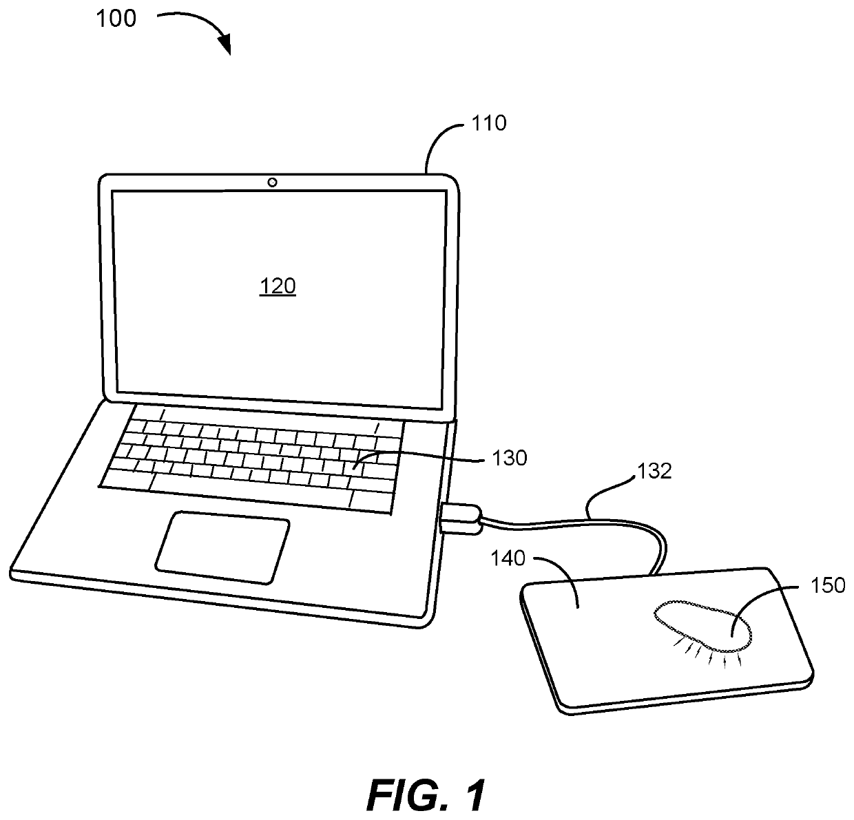
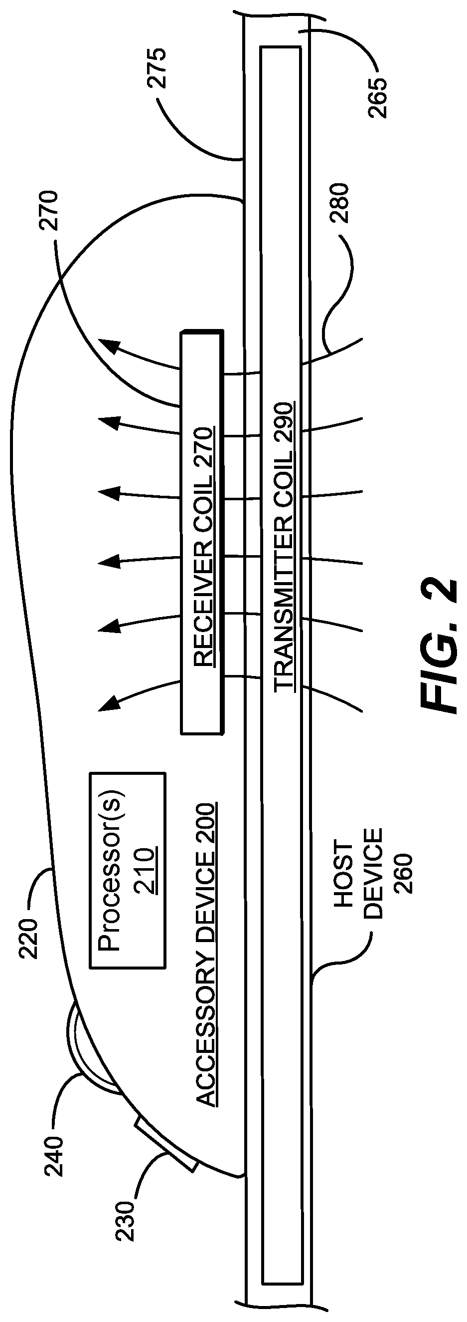
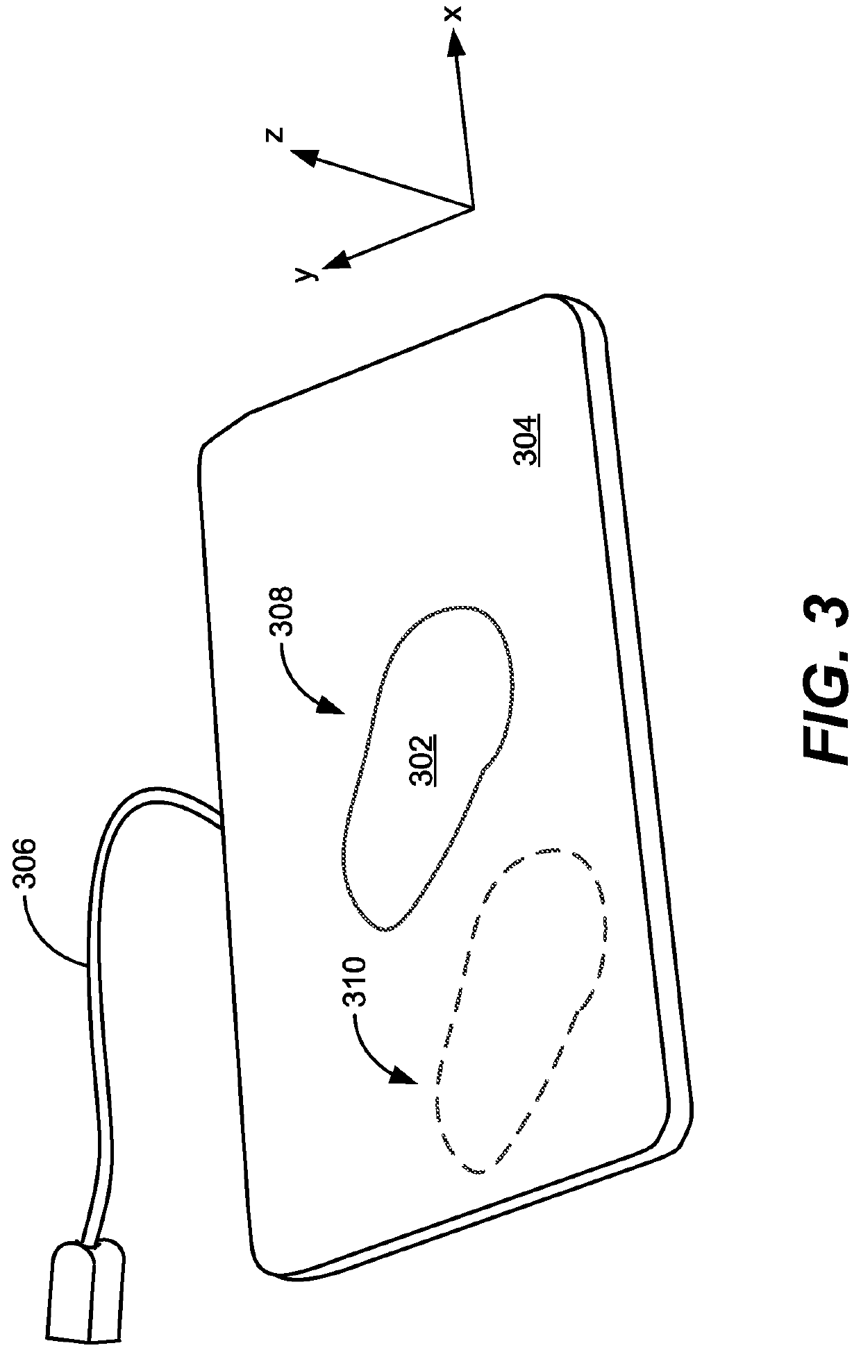
[0020]Embodiments of the disclosure provide systems and methods for improved wireless charging of an accessory device via a host device that also functions as a mouse pad upon which the accessory device can move. The host device can be a charging mouse pad that includes an inductive transmitter coil to wirelessly and electromagnetically trans...


PUM


Abstract

Embodiments describe a wireless charging system including an accessory device and a host device. The host device can include a housing having a charging surface and power transmitting circuitry coupled to a power source. The power transmitting circuitry can include an inductive transmitter coil configured to receive a first power and generate magnetic field, an amplifier coupled to the inductive transmitter coil and configured to output the first power to the inductive transmitter coil, an output sensor coupled to the inductive transmitter coil and configured to measure the first power to the inductive transmitter coil, and a power tracking controller coupled to the sensor probe. The power tracking controller can be configured to receive measurement of the first power, and generate a control signal based on the measured first power to modify an output impedance of the amplifier to output a second power different from the first power.

Description

BACKGROUND[0001]Wireless peripheral devices (e.g., computer mice, keyboards, speakers, ear buds, smart wearables, etc.) are widely used and provide portability and convenience, but often suffer from poor battery life. Although battery technology continues to improve, most peripheral devices require a charging cable for extended usage, which can be cumbersome, limiting, and defeat the purpose of wireless technology in general. Some contemporary charging schemes solve this problem by utilizing a charging base to wirelessly charge a peripheral device over time. Improved methods of wireless charging are needed.BRIEF SUMMARY[0002]In some embodiments, wireless charging system includes an accessory device and a host device. The accessory device can include a processor configured to operate the accessory device, a receiver coil configured to interact with a magnetic field to generate an electrical current, and power receiving circuitry coupled to the receiver coil and the processor, the pow...

Claims


Application Information

Patent Timeline
Patent Type & Authority Applications(United States)
IPC IPC(8): H02J7/02H02J50/12G06F3/0354G06F3/039G06F3/038
CPCG06F3/038H02J50/12H03K19/21G06F3/03543G06F3/0395H02J7/025H02J50/80
Inventor VLASOV, MAXIMPLANCHEREL, LAURENT
Owner LOGITECH EURO SA
Learn More