Distance Measurement Unit

a distance measurement and unit technology, applied in the direction of measuring devices, instruments, using reradiation, etc., can solve the problems of allowing the time offset between the pulses emitted sequentially in the same solid angle segment to become too large, the echo pulse can become so small, and no suitable signal can be obtained

Pending Publication Date: 2020-11-12
OSRAM BETVERWALTUNG GMBH
View PDF1 Cites 0 Cited by
  • Summary
  • Abstract
  • Description
  • Claims
  • Application Information

AI Technical Summary

Problems solved by technology

Similarly, it may be of interest not to allow the time offset between the pulses emitted sequentially in the same solid angle segment to become too large.
For example, in the case of a very distant or unfavorable object (reflection properties, etc.) the echo pulse can become so small that no suitable signal can be obtained even by signal processing (merging several successive echo pulses).

Method used


Image

  • Distance Measurement Unit
  • Distance Measurement Unit
  • Distance Measurement Unit

Examples


Embodiment Construction

[0059]FIGS. 1a,b show a distance measuring unit 1, which is installed in a motor vehicle 2 and aligned in the direction of travel (forward). With the distance measuring unit 1, the distance to objects 3a,b, such as other vehicles or even pedestrians etc., can be measured if these objects 3a,b are located in the detection field 4 of the distance measuring unit 1. The detection field 4 has a horizontal opening angle a and a vertical opening angle β.

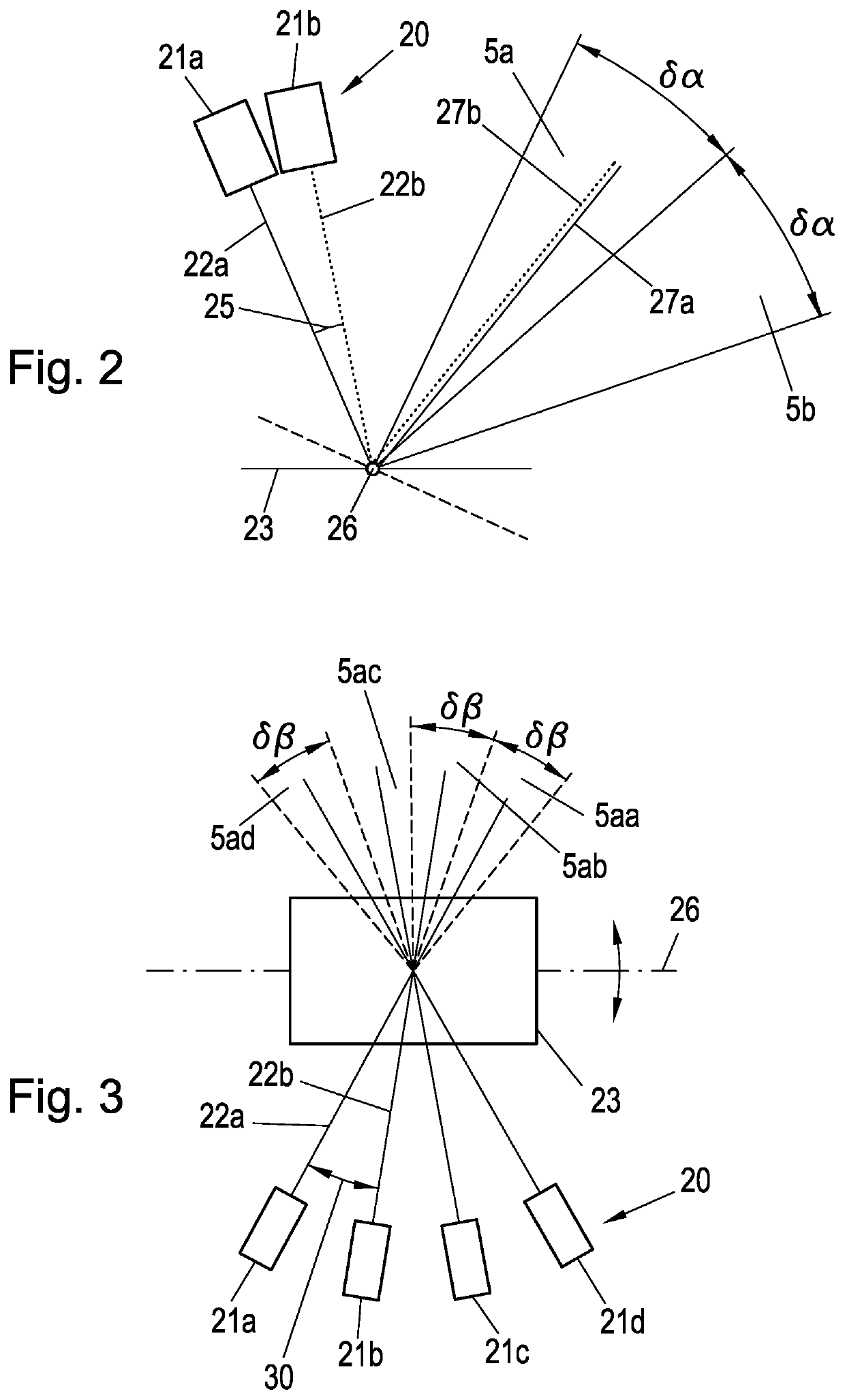
[0060]As then explained in detail based on FIG. 2, the detection field 4 is subdivided horizontally into a number of solid angle segments 5a,b, which result from a pulsed emission via a tiltable (and moving) mirror. Each of the solid angle segments 5a,b corresponds to a mirror angular position, wherein a respective pulse 6 is guided into the respective solid angle segment 5a,b via the mirror. If there is an object located in the respective solid angle segment 5a,b, the pulse is reflected, so it comes back as an echo pulse and can be receive...


PUM


Abstract

Various implementations disclosed herein include a distance measuring unit for signal transition time-based measurement of a distance to an object located in a detection field, with an emitter unit with multiple emitters, each designed to emit pulses in the form of electromagnetic radiation, a receiver unit for receiving the electromagnetic radiation after a distance-dependent transition time, and a tiltable mirror, wherein the distance measuring unit is configured such that a first of the emitters emits multiple pulses sequentially via the mirror, including at a first time in a first solid angle segment in a first angular position of the mirror, and at a second time in a second solid angle segment in a second angular position of the mirror; and a second of the emitters also emits a pulse in at least one of the solid angle segments via the mirror.

Description

TECHNICAL AREA[0001]The present invention relates to a distance measuring unit for signal transition time-based distance measurement.PRIOR ART[0002]The distance measurement in question is based on a transition time measurement of emitted electromagnetic pulses. If these are incident on an object, the pulse is proportionally reflected at its surface back to the distance measuring unit and can be recorded as an echo pulse with a suitable sensor. If the pulse is sent out at a time t0 and the echo pulse is detected at a later time t1, the distance d to the reflective surface of the object can be determined from the transition time ΔtA=t1−t0 according tod=ΔtA c / 2   Eq. 1.Since this is an electromagnetic pulse, c is the value of the speed of light.Representation of the Invention[0003]The present invention is based on the technical problem of specifying a particularly advantageous distance measuring unit.[0004]This is solved according to the invention with a distance measuring unit as clai...

Claims


Application Information

Patent Timeline
Patent Type & Authority Applications(United States)
IPC IPC(8): G01S7/481G01S17/10G01S17/931G01S7/4863
CPCG01S7/4815G01S7/4817G01S17/931G01S17/10G01S17/42G01S7/4808G01S7/4816G01S7/484G01S7/4863
Inventor NAUEN, ANDRE
Owner OSRAM BETVERWALTUNG GMBH
Why Eureka
Try Eureka