Driving assistance apparatus
a technology of assistance apparatus and driver, which is applied in the direction of control devices, external condition input parameters, instruments, etc., can solve problems such as annoy drivers, and achieve the effect of reducing risk and reducing annoyance for drivers
- Summary
- Abstract
- Description
- Claims
- Application Information
AI Technical Summary
Benefits of technology
Problems solved by technology
Method used
Image

Examples
first embodiment
[0020]Hereinbelow, a first embodiment will be described with reference to the drawings.
[0021]A driving assistance apparatus 1 is mounted on an own vehicle V which is an automobile, and performs notification (described below) to a driver of the own vehicle V.
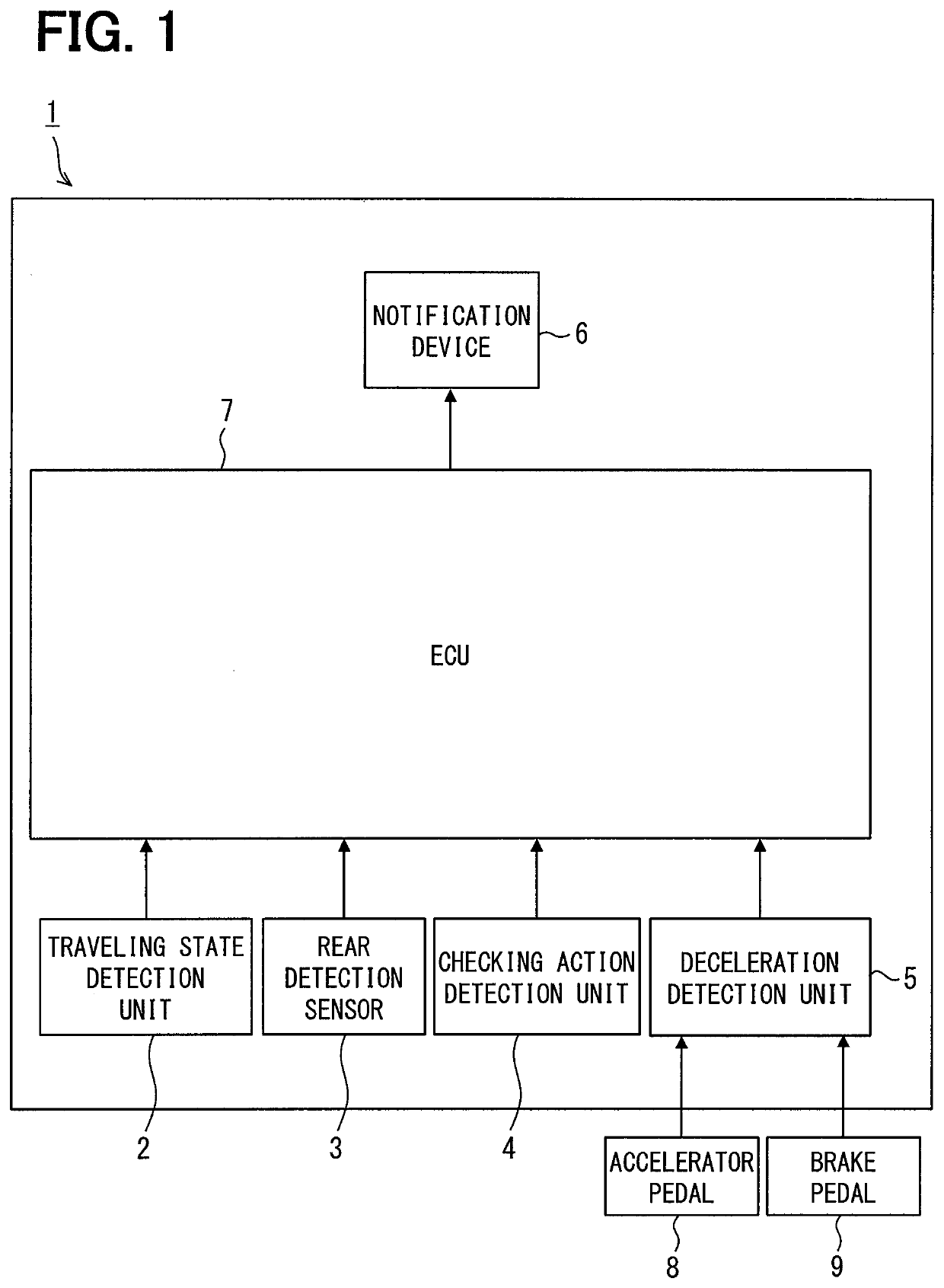
[0022]As illustrated in FIG. 1, the driving assistance apparatus 1 includes a traveling state detection unit 2, a rear detection sensor 3, a checking action detection unit 4, a deceleration detection unit 5, a notification device 6, and an ECU 7. The deceleration detection unit 5 is connected to an accelerator pedal 8 and a brake pedal 9.
[0023]The traveling state detection unit 2 detects a traveling state of the own vehicle V and outputs the detected traveling state to the ECU 7 (described below). The traveling state described herein indicates whether the own vehicle V is in a traveling state or a stopped state. Further, in the traveling state, there is a distinction between forward traveling and backward traveling.
[0024]In order...
second embodiment
[0061]Hereinbelow, a second embodiment will be described with reference to the drawings.
[0062]A traveling state detection unit 2 in the second embodiment detects or calculates a tilt angle of the own vehicle V with respect to a horizontal plane, in addition to detect or calculate a speed or an acceleration in traveling of the own vehicle V, to detect a traveling state. Then, a determination period of the deceleration determination for the own vehicle V illustrated in FIG. 6 described in the first embodiment is determined on the basis of the detected tilt angle. The traveling state detection unit 2 in the second embodiment includes a tilt angle sensor (not illustrated) for detecting or calculating the tilt angle of the own vehicle V with respect to the horizontal plane. For example, a known gyro sensor can be used as the tilt angle sensor. A kwon detection algorithm can be used as a method for detecting the tilt angle of the own vehicle V.
[0063]Next, a series of processes according t...
third embodiment
[0071]In a third embodiment, in addition to the “alert” and the “warning”, “notice notifying the presence of a vehicle” is added to the notification to the driver performed in the notification device 6.
[0072]The notice notifying the presence of a vehicle is notice for notifying that the rear vehicle R is present behind the own vehicle V. On the other hand, the alert and the warning are alert and warning for notifying the driver of the possibility of collision between the own vehicle V and the rear vehicle R.
[0073]In the third embodiment, the timing of performing alert notification to the driver is added.
[0074]The notice notifying the presence of a vehicle is performed to the driver immediately when a state in which the driver is unaware of the rear vehicle R comes into existence. The state in which the driver is unaware of the rear vehicle R is a state in which the own vehicle V is traveling, the rear vehicle R is present within the first range, and the driver has not checked behind...
PUM
 Abstract
Description
Claims
Application Information
 - R&D
- Intellectual Property
- Life Sciences
- Materials
- Tech Scout
- Unparalleled Data Quality
- Higher Quality Content
- 60% Fewer Hallucinations
Browse by: Latest US Patents, China's latest patents, Technical Efficacy Thesaurus, Application Domain, Technology Topic, Popular Technical Reports.
© 2025 PatSnap. All rights reserved.Legal|Privacy policy|Modern Slavery Act Transparency Statement|Sitemap|About US| Contact US: help@patsnap.com