Eureka AIR delivers breakthrough ideas for toughest innovation challenges, trusted by R&D personnel around the world.

Camera mount system

a camera and mount technology, applied in the field of camera mount systems, can solve the problems of not being able to directly look at the shooter, unable to record distant video or images, and being unable to meet the needs of the shooter,

Active Publication Date: 2020-02-06
TACTACAM LLC
View PDF6 Cites 15 Cited by
  • Summary
  • Abstract
  • Description
  • Claims
  • Application Information

AI Technical Summary

Benefits of technology

The patent describes a camera mount system that can be used for photos and videos. The system has various advantages and innovative features that make it easy to use and capture high-quality images.

Problems solved by technology

Recording distant video or images through a scope can suffer from a multitude of difficulties.
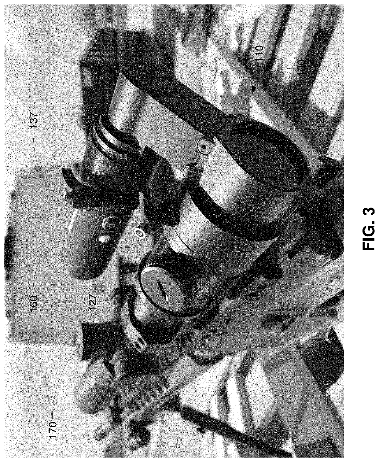
This can be a rather bulky, off-center configuration in which the shooter no longer directly looks through the optics of the scope.
This can cause inaccurate and / or inconsistent shots.
Not only does this cause eye strain for the shooter, but also impedes the shooter's ability to locate and / or track the moving target.
Finally, the smartphone is difficult to optically align and moves out of optical alignment especially when shooting a high recoil rifle.
Such scope displays are stressful for eyes focusing on such as a close display, which can make it difficult for the shooter to locate a target (e.g., a moving target).
These repeated eye adjustments can be the cause of stress and strain on the eye.
Further, since the scope is electronic, the scope cannot be used if the battery runs out of energy.
However, such configurations are unwieldy.
Moreover, the alignment between the camera and the aiming point of the rifle can be inconsistent for the shooter.
In addition, the camera does not provide the shooter's view (e.g., a first person shooter's view), but instead provides a view from a different angle and not the view through the scope.

Method used


Image

  • Camera mount system
  • Camera mount system
  • Camera mount system

Examples


Embodiment Construction

[0022]As utilized herein, “and / or” means any one or more of the items in the list joined by “and / or”. As an example, “x and / or y” means any element of the three-element set {(x), (y), (x, y)}. As another example, “x, y, and / or z” means any element of the seven-element set {(x), (y), (z), (x, y), (x, z), (y, z), (x, y, z)}. As utilized herein, the term “exemplary” means serving as a non-limiting example, instance, or illustration. As utilized herein, the terms “e.g.” and “for example” set off lists of one or more non-limiting examples, instances, or illustrations.

[0023]The drawings are of illustrative embodiments. They do not illustrate all embodiments. Other embodiments may be used in addition or instead. Details that may be apparent or unnecessary may be omitted to save space or for more effective illustration. Some embodiments may be practiced with additional components or steps and / or without all of the components or steps that are illustrated.

[0024]Some embodiments according to ...


PUM


Abstract

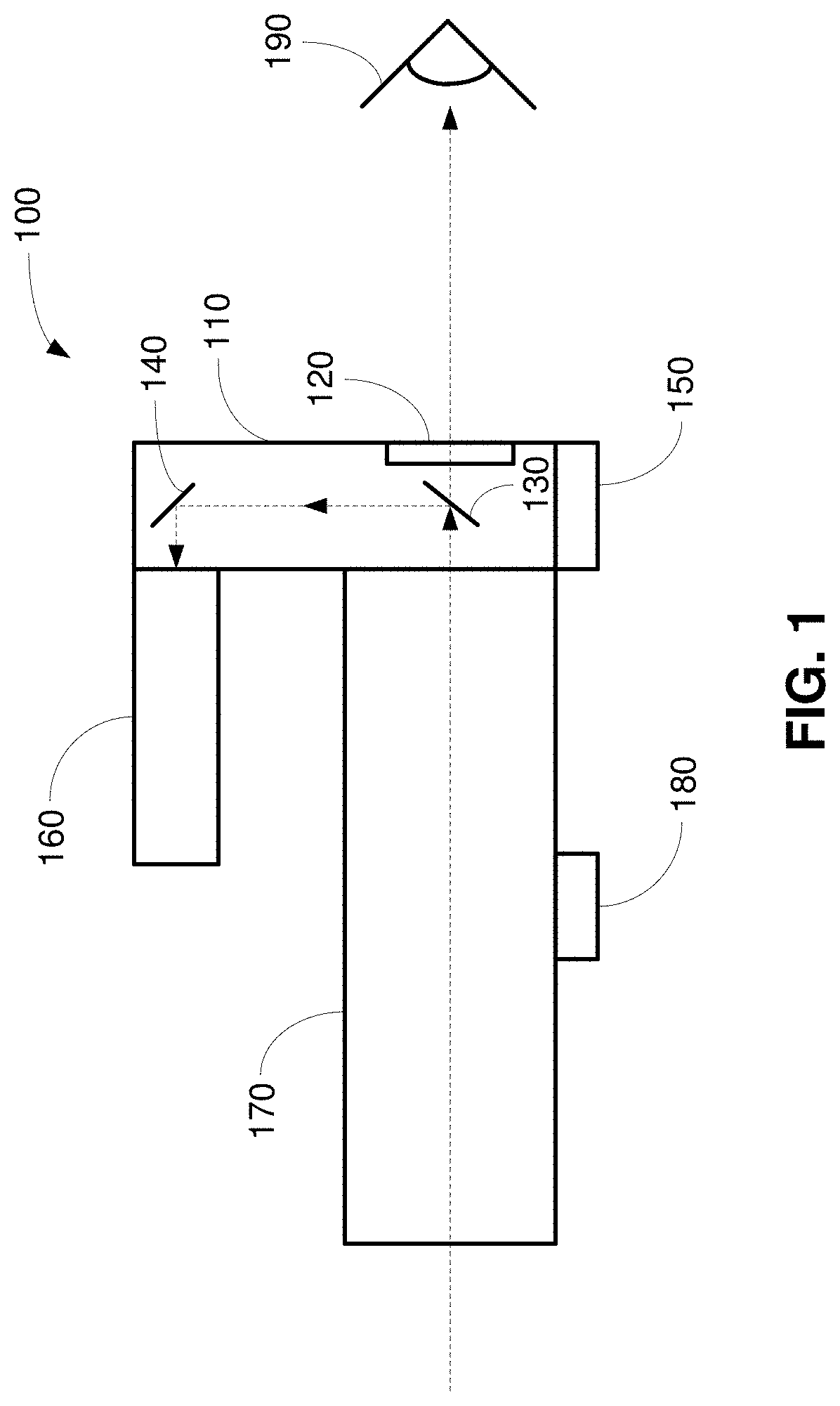
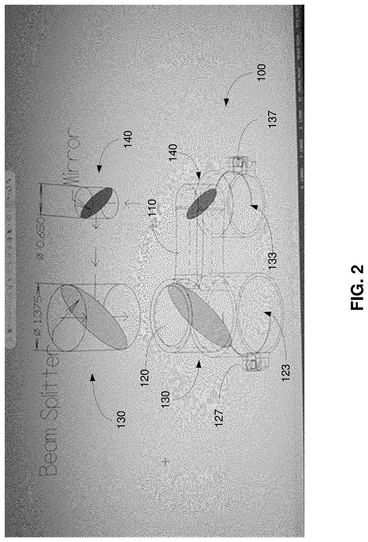
Systems, apparatuses, and methods are described which provide a camera mount system. The camera mount system can include, for example, a first optical element and a second optical element. Incoming light from a scope on a weapon, for example, is partially transmitted and partially reflected by the first optical element. The partially transmitted light passes through an eyepiece to a viewer (e.g., a shooter). The partially reflected light is reflected by the second optical element and is recorded by a recording device (e.g., a camera, a video recorder, an image sensor, etc.). The viewer has direct access to the scope optics, a spotting scope, or binoculars, for example, and the camera and the viewer have access to the same view.

Description

RELATED APPLICATIONS / INCORPORATION BY REFERENCE[0001]The present application benefits from and claims priority to U.S. Application No. 62 / 790,453, filed Jan. 9, 2019, and U.S. Application No. 62 / 715,031, filed Aug. 6, 2018. The above-identified applications are hereby incorporated herein by reference in their entirety.BACKGROUND[0002]Recording distant video or images through a scope can suffer from a multitude of difficulties.[0003]For example, a smartphone can be secured behind a scope on a rifle. This can be a rather bulky, off-center configuration in which the shooter no longer directly looks through the optics of the scope. Instead of directly looking through the scope, the shooter must adjust to a different positioning (e.g., the off-center positioning since the smartphone camera is located in a corner of the smartphone housing) of the smartphone and the height and width of the display of the smartphone. Typically, the human eye has a hard time focusing on objects that are appr...

Claims


Application Information

Patent Timeline
Patent Type & Authority Applications(United States)
IPC IPC(8): G03B29/00F41C27/00F41G11/00
CPCG03B29/00F41C27/00F41G11/001F41J5/10F41G1/38F41G1/17G03B17/566
Inventor PEEL, JEFFREY B.PEEL, GARRISON J.STERN, BENJAMIN B.
Owner TACTACAM LLC
Why Eureka
Eureka Blog
Learn More