Work Vehicle
- Summary
- Abstract
- Description
- Claims
- Application Information
AI Technical Summary
Benefits of technology
Problems solved by technology
Method used
Image

Examples
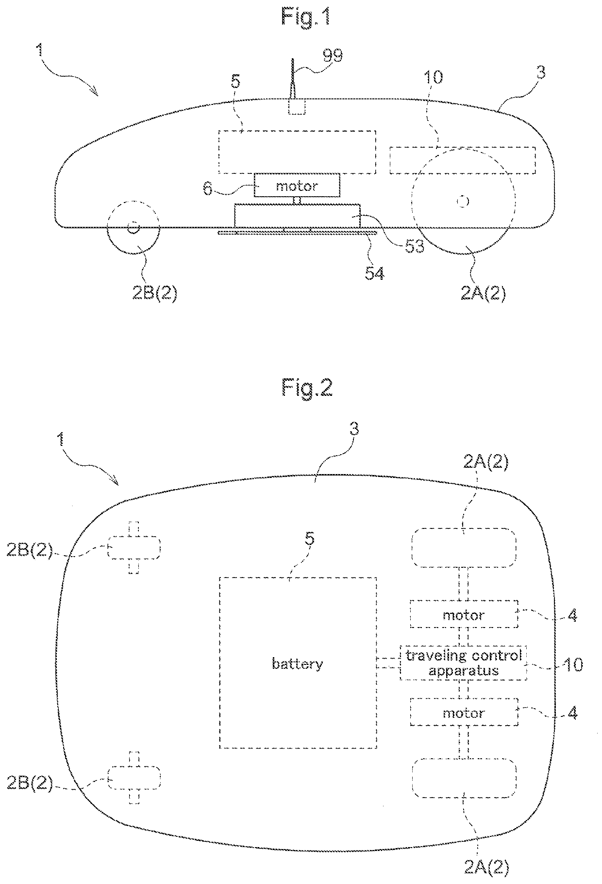
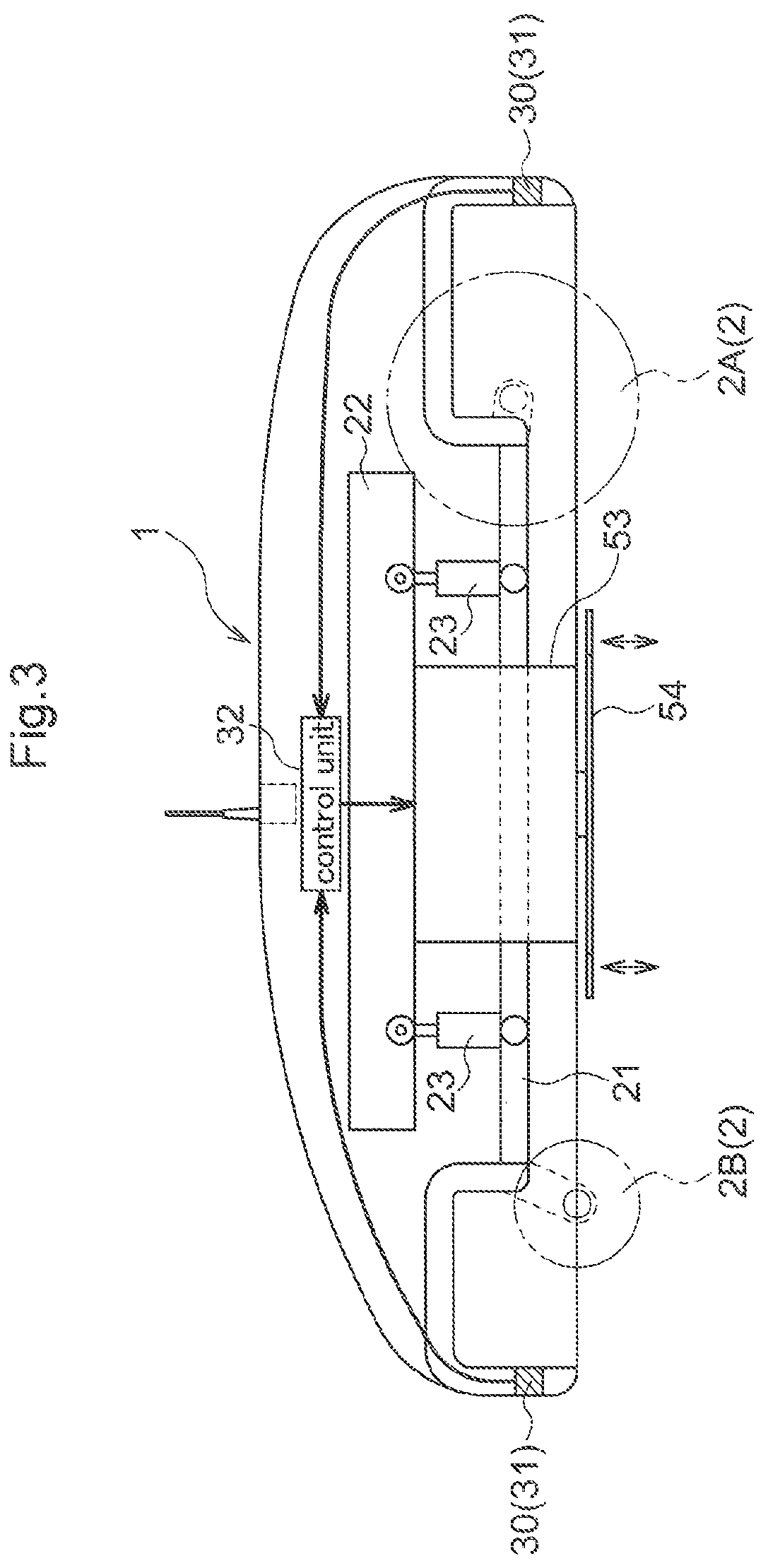
first embodiment
Variations of First Embodiment
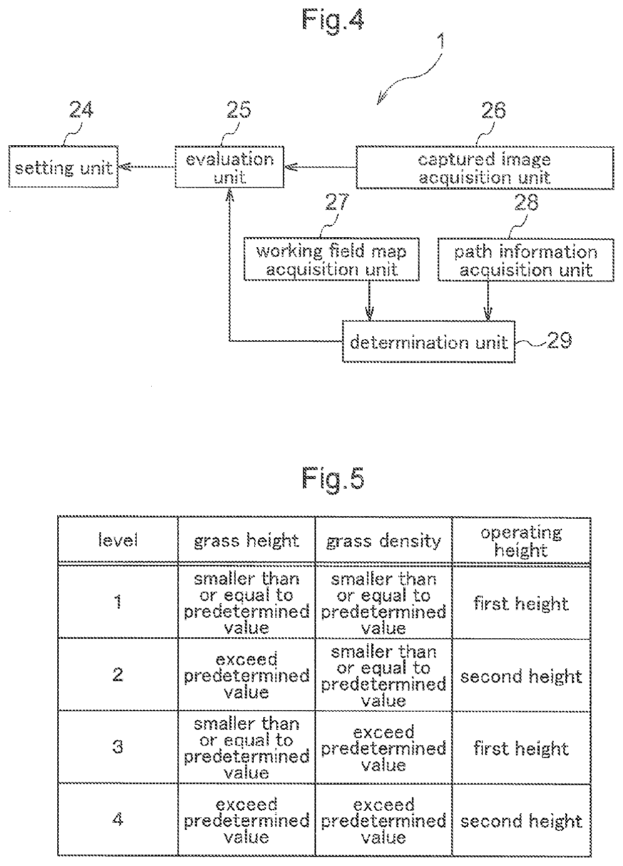
[0067]In the above-described embodiment, the evaluation unit 25 evaluates the grass height and the grass density of lawn grass, and the setting unit 24 sets the operating height in accordance with the evaluation result from the evaluation unit 25. However, the setting unit 24 can alternatively be configured to set the operating height regardless of the evaluation result from the evaluation unit 25. In this case, the work vehicle 1 may not be provided with the evaluation unit 25.
[0068]In the above-described embodiment, the captured image acquisition unit 26 acquires a captured image of a working field, and the evaluation unit 25 evaluates the grass height and grass density of lawn grass based on the captured image. However, the evaluation unit 25 can alternatively be configured to evaluate the grass height and grass density of lawn grass without using a captured image.
[0069]In the above-described embodiment, the working field map acquisition unit 27 acqu...
second embodiment
Variations of Second Embodiment
[0089]In the above-described embodiment, the load reduction unit 158 is provided in the front portion of the vehicle body relative to the traveling direction, and the operation completion unit 159 is provided in the rear portion of the vehicle body relative to the traveling direction. However, as shown in FIG. 8, the operation completion unit 159 may alternatively be provided in the center portion of the vehicle body as viewed from above, and the load reduction unit 158 may alternatively be provided so as to surround the operation completion unit 159 as viewed from above the vehicle body. In this case, it is favorable that the operation completion unit 159 provided in the center portion is a reel or a rotary blade for fine cutting, which needs to be accurate, and the load reduction unit 158 provided around the operation completion unit 159 is a flail mower or a clipper mower. With this configuration as well, the load reduction unit 158 can reduce the l...
PUM
 Abstract
Description
Claims
Application Information
 - R&D
- Intellectual Property
- Life Sciences
- Materials
- Tech Scout
- Unparalleled Data Quality
- Higher Quality Content
- 60% Fewer Hallucinations
Browse by: Latest US Patents, China's latest patents, Technical Efficacy Thesaurus, Application Domain, Technology Topic, Popular Technical Reports.
© 2025 PatSnap. All rights reserved.Legal|Privacy policy|Modern Slavery Act Transparency Statement|Sitemap|About US| Contact US: help@patsnap.com