Eureka AIR delivers breakthrough ideas for toughest innovation challenges, trusted by R&D personnel around the world.

Automatic spring fastener assembly machine

a technology of automatic spring fastener and assembly machine, which is applied in the direction of manufacturing tools, transportation and packaging, metal working apparatus, etc., can solve the problems of low production efficiency and increase labor costs, and achieve the effects of improving working efficiency, convenient operation, and fast and efficient completion

Active Publication Date: 2019-11-07
DONGGUAN UNIV OF TECH
View PDF0 Cites 66 Cited by
  • Summary
  • Abstract
  • Description
  • Claims
  • Application Information

AI Technical Summary

Benefits of technology

The present invention provides a fastener assembly device that works quickly and efficiently, using a circulating conveying device and a fastener pushing in device. The design of the device prevents jamming and ensures the normal operation. The rubber casing clamping device makes assembly easier, and the fastener pushing in device completes the assembly of multiple spring fasteners in one time, increasing production efficiency. Overall, the technical effects of the invention are fast assembly, ease of operation, and high efficiency.

Problems solved by technology

During assembly, due to the small size of the workpiece, manual assembly is time-consuming and labor-intensive, and assembly is inconvenient, thereby production efficiency is low and labor cost increases.

Method used


Image

  • Automatic spring fastener assembly machine
  • Automatic spring fastener assembly machine
  • Automatic spring fastener assembly machine

Examples


Embodiment Construction

[0109]The present invention will be described in detail below with reference to the accompanying drawings, the description of the present invention is only exemplary and explanatory, and should not be construed as limiting the scope of the present invention.

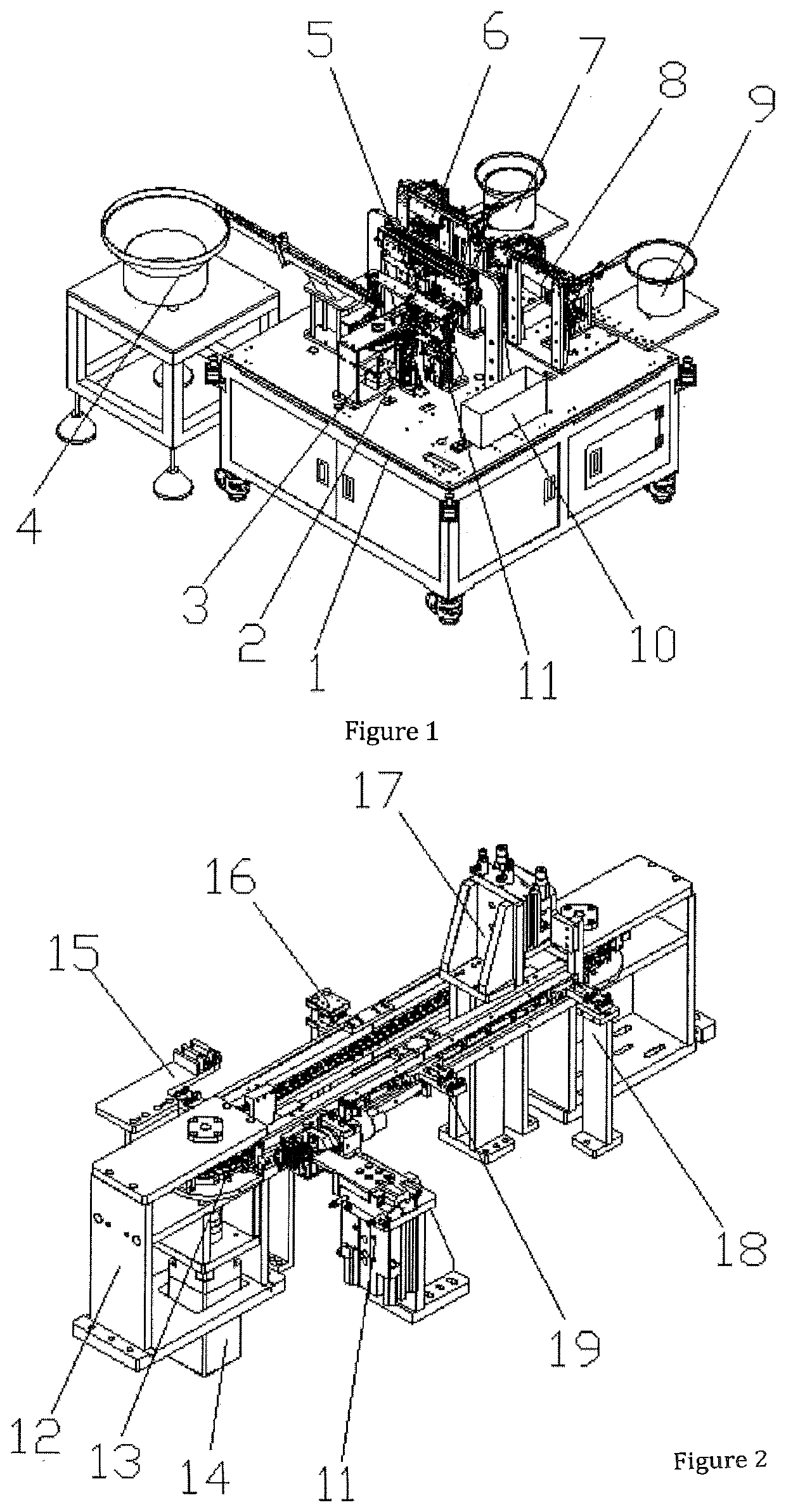
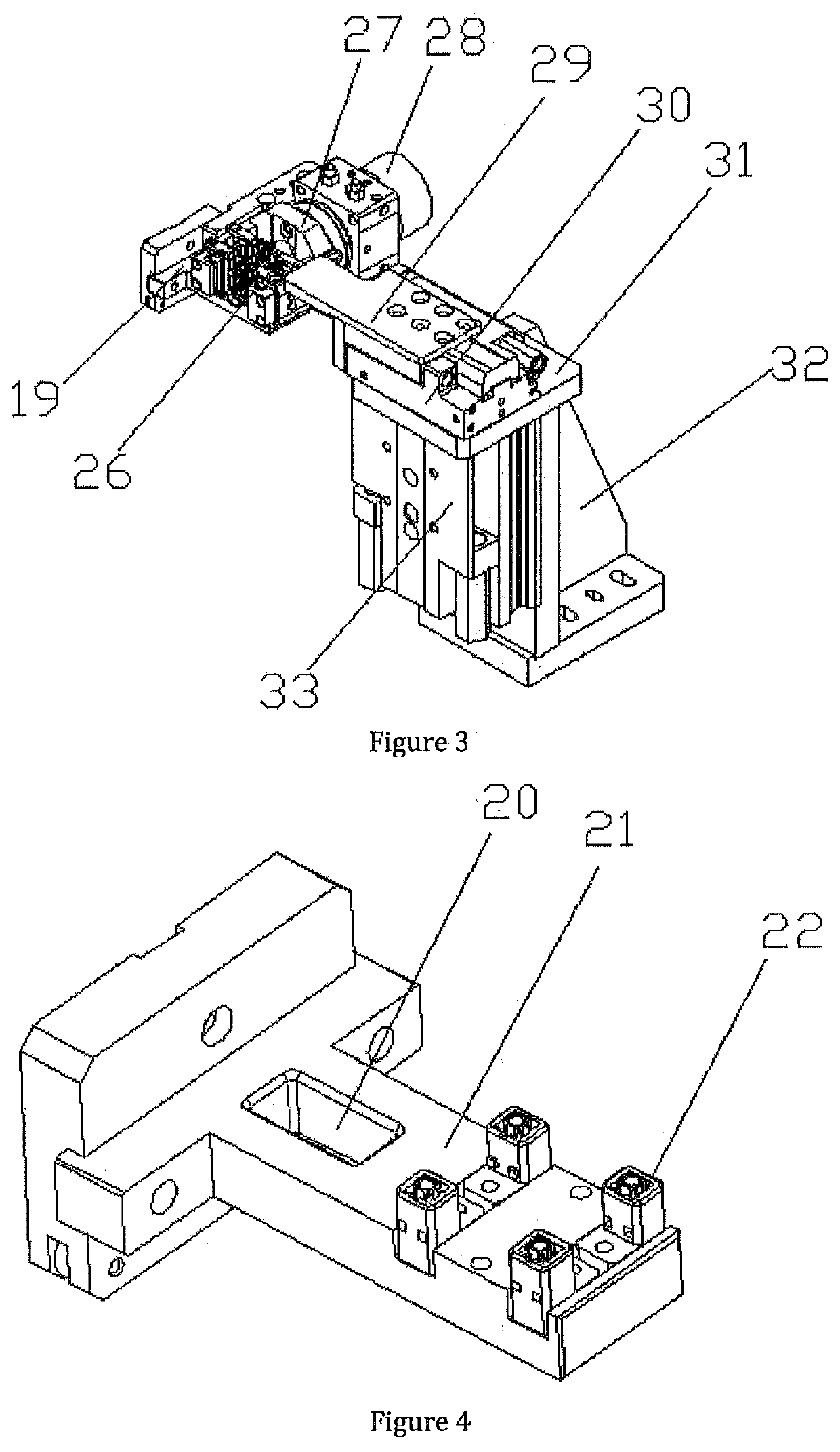
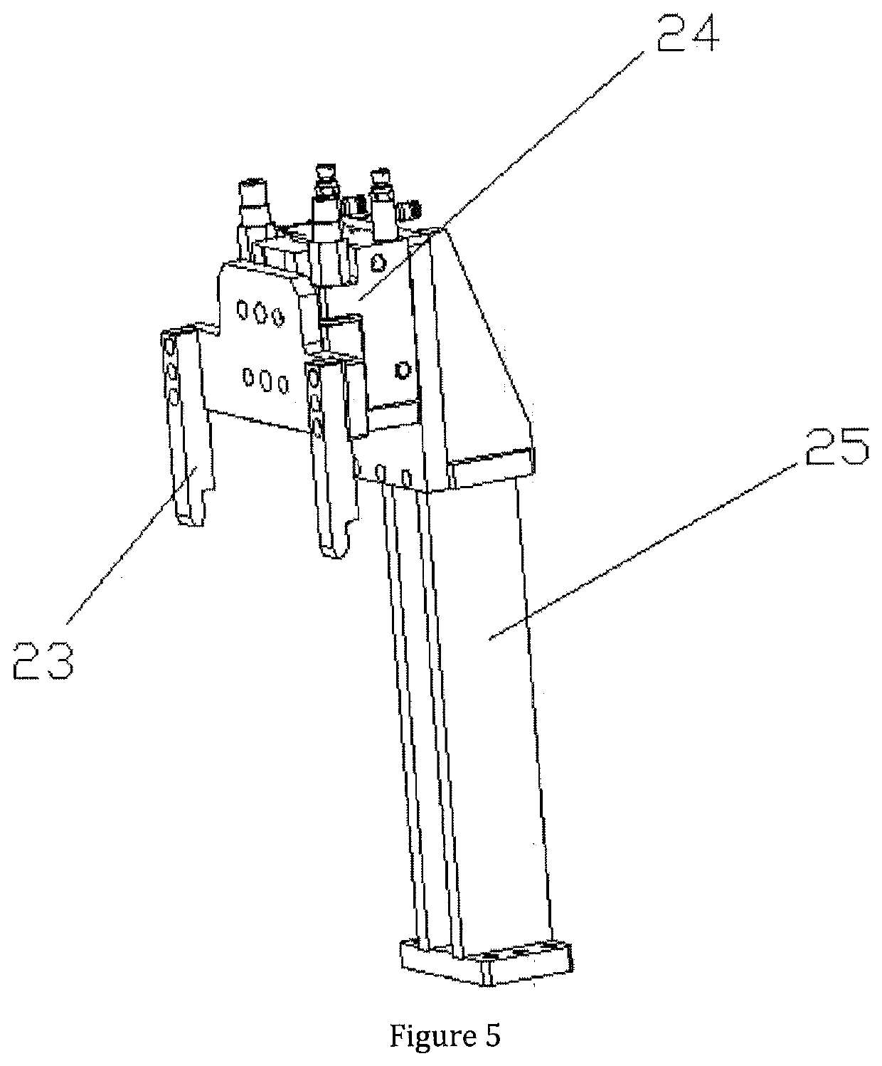
[0110]As shown in FIGS. 1-13, the structure of the present invention is: an automatic spring fastener assembly machine, including a rack 1 and a power control box, the rack 1 is provided with a circulating conveying device 3, and a rubber casing feeding device, fastener feeding device and spring loading device, which are sequentially disposed around the circulating conveying device 3; the rubber casing feeding device includes a rubber casing feeding vibration tray 4 disposed to the left front side of the circulating conveying device 3, and the rubber casing feeding vibration tray 4 is connected with a rubber casing distributing block 15 through a rubber casing conveying track, a rubber casing transportation manipulator 5 fitting ...


PUM

PropertyMeasurementUnit
sizeaaaaaaaaaa
stabilityaaaaaaaaaa
gravityaaaaaaaaaa

Abstract

The present invention relates to an automatic spring fastener assembly machine, including a rack and a power control box, and the rack is provided with a circulating conveying device, and a rubber casing feeding device, a fastener feeding device and a spring loading device which are in turn arranged around the circulating conveying device. The rubber casing feeding device includes a rubber casing vibration tray disposed to the left front side of the circulating conveying device, and the rubber casing feeding vibration tray is connected with a rubber casing distributing block through the rubber casing conveying track. The upper side of the circulating conveying device is provided with a rubber casing transportation manipulator, and the right front side thereof is provided with a rubber casing clamping device located below the rubber casing transportation manipulator, and a fastener pushing in device fitting the circulating conveying device is disposed under the rubber casing clamping device. In the present invention, material feeding and conveying is done by the circulating conveying device, and fasteners are fitted into corresponding holes on the rubber casings from a higher position with the fastener pushing in device, which can be completed fast and efficiently, is easy to operate, realize quick assembly of spring fasteners and improve working efficiency.

Description

FIELD OF THE INVENTION[0001]The present invention relates to a non-standard part automatic assembly machine, and more particularly to an automatic spring fastener assembly machine.BACKGROUND OF THE INVENTION[0002]There is a new type of spring fastener, the structure thereof being shown in FIG. 13, which includes a rubber casing 69 and four sockets 70 disposed on the surface of the rubber casing 69. A spring and a fastener 71 are sequentially plugged into the sockets 70, and the fastener 71 is snap-fitting the socket 70. During assembly, due to the small size of the workpiece, manual assembly is time-consuming and labor-intensive, and assembly is inconvenient, thereby production efficiency is low and labor cost increases.SUMMARY OF THE INVENTION[0003]The object of the present invention relates to an automatic spring fastener assembly machine, material feeding and conveying is done by the circulating conveying device, and fasteners are fitted into corresponding holes on the rubber cas...

Claims


Application Information

Patent Timeline
Patent Type & Authority Applications(United States)
IPC IPC(8): B23P19/04B23P19/00B65G47/82B65G27/04
CPCB65G27/04B23P19/002B23P19/006B65G2812/03B23P19/048B65G47/82H01R43/20B23P19/001B23P19/04B23P19/004B23P19/008B23P19/107B23P19/12B23P21/004Y10T29/49609
Inventor LI, CHUANBAI, YUN
Owner DONGGUAN UNIV OF TECH
Why Eureka
Eureka Blog
Learn More