
Breast subcutaneous tissue surgical instruments

a surgical instrument and breast tissue technology, applied in the field of breast subcutaneous tissue surgical instruments, can solve the problems of breast tissue necrosis or other post-operation complications, the procedure is not optimized for the anatomy of the breast tissue, and the risk of many complications

Inactive Publication Date: 2019-10-03
WESTERN NEW ENGLAND UNIVERSITY
View PDF0 Cites 3 Cited by
  • Summary
  • Abstract
  • Description
  • Claims
  • Application Information

AI Technical Summary

Benefits of technology

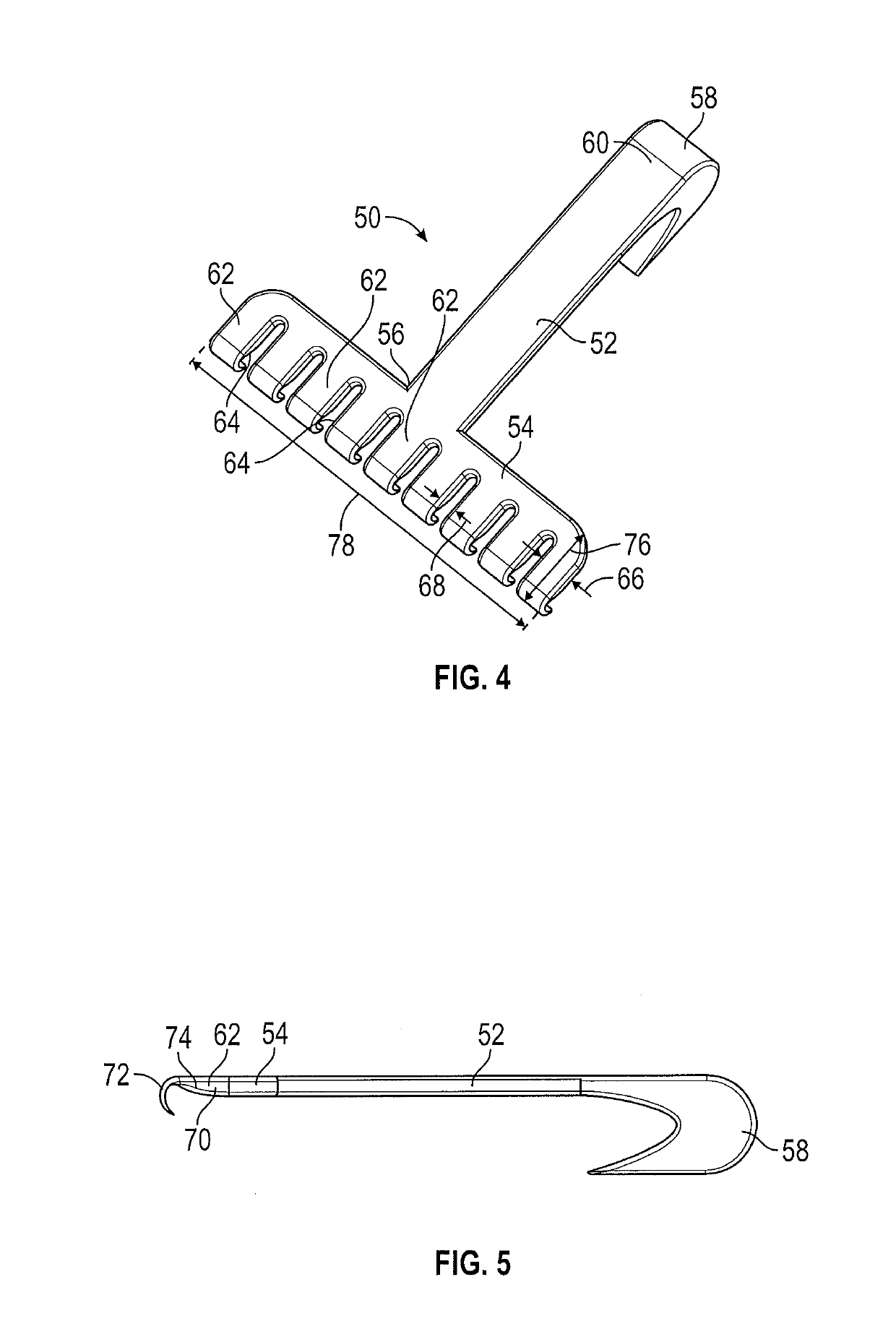
The patent describes a dilator and retractor for separating subcutaneous fat from glandular tissue. The dilator has a unique design with a center section, first and second end sections, and different diameters. The retractor has a handle, shaft, and head with unevenly spaced teeth. The tooth ends have a curved profile that defines a V-shaped or curvilinear profile. The dilator and retractor can be used together in a dilator set for more effective fat removal. The technical effects of the invention include improved fat separation with reduced damage to surrounding tissue, reduced bleeding, and improved aesthetic outcomes.

Problems solved by technology

This procedure poses the risk of many complications because the space between the two tissues to be separated is thin, and the dissection extends down to the chest wall.
During such a procedure, the skin or surrounding blood vessels may be punctured by the scalpel, which may lead to tissue necrosis or other post-operation complications.
Current available dilators, however, are designed for other uses and are not optimized for the anatomy of the breast tissue.

Method used


Image

  • Breast subcutaneous tissue surgical instruments
  • Breast subcutaneous tissue surgical instruments
  • Breast subcutaneous tissue surgical instruments

Examples


Embodiment Construction

[0035]A detailed description of one or more embodiments of the disclosed apparatus and method are presented herein by way of exemplification and not limitation with reference to the Figures.

[0036]Referring to FIG. 1, illustrated is an embodiment of a dilator 10, configured for use in separating subcutaneous fat from glandular beast tissue during a mastectomy procedure. The dilator 10 is C-shaped, with a center section 12, a first end section 14 and a second end section 16, opposite the first end section 14. The first end section 14 and the second end section 16 each have a circular cross-section, with the first end section 14 having a first end diameter 18 and the second end section 16 similarly has a second end diameter 20. The first end diameter 18 is different from the second end diameter 20.

[0037]The first end section 14 includes a first end tip 22, and the second end section 16 similarly includes a second end tip 24. In some embodiments, the first end tip 22 and the second end ...


PUM


Abstract

A dilator configured for separating subcutaneous fat from glandular tissue includes a center section, a first end section extending from a first end of the center section, the first end section extending nonparallel to the center section, the first end section having a first diameter, and a second end section extending from a second end of the center section opposite the first end, the second end section extending nonparallel to the center section, the second end section having a second diameter different than the first diameter. A retractor includes a handle, a shaft extending from the handle, and a head located at a shaft end opposite the handle. The head includes a plurality of teeth, each tooth having a tooth end curving downwardly from a head outer surface, adjacent teeth spaced from one another by a tooth gap therebetween, the plurality of teeth having unequal tooth lengths.

Description

CROSS-REFERENCE TO RELATED APPLICATIONS[0001]The present application is a Non-provisional Application of U.S. Provisional Application Ser. No. 62 / 650,481 filed on Mar. 30, 2018, the contents of which is incorporated by reference in its entirety.BACKGROUND[0002]Exemplary embodiments pertain to the art of surgical instruments. In particular, the present disclosure relates to surgical instruments for separating subcutaneous fat from glandular breast tissue during a mastectomy procedure.[0003]In treating breast cancer patients, the type of surgical procedure performed, if any, depends on the size and site of the tumor, characteristics of the tumor cells, the stage of the disease and the patient's choice. In breast conserving surgery, only the tumor and some surrounding tissue is removed. In another procedure, called a mastectomy, the entire breast and any surrounding infected areas are removed.[0004]The current method to perform a mastectomy includes creating an incision around the brea...

Claims


Application Information

Patent Timeline
Patent Type & Authority Applications(United States)
IPC IPC(8): A61B17/02A61M29/00
CPCA61B17/02A61B2017/0042A61B2017/0212A61B2017/008A61M29/00A61B2017/320044A61B17/320708A61B2017/00796
Inventor SCHONHOLZ, STEVEN MICHAELGETTENS, ROBERT TREAT THOMPSONBRANSCOMB, JAY MICHAELKOZLOWSKI, KARISSAKOSS, JR., STEVEN
Owner WESTERN NEW ENGLAND UNIVERSITY
Learn More