
Electronically controlled window

a technology of electric motors and windows, applied in the field of electric motors, can solve the problems of time-consuming and stressful overall process of manually opening and closing windows, and the lack of efficiency of manually controlling windows,

Active Publication Date: 2019-07-18
FLOE WAYNE
View PDF20 Cites 2 Cited by
  • Summary
  • Abstract
  • Description
  • Claims
  • Application Information

AI Technical Summary

Benefits of technology

The present invention introduces an electronically powered window for a watercraft. By using a shuttle frame, sliding mechanism, window pane, and bottom edge support groove, the window can be opened and closed by controlling a switch. This eliminates the need for manual control of the window, which can be time-consuming and stressful. The size of the window can vary, and the design of the boat can incorporate windows of different sizes. The overall efficiency of the electronically powered window is greater than traditional windows, as it allows for greater efficiency in controlling the windows.

Problems solved by technology

As an example, during rainy and windy conditions, the windows of the boat need to be closed.
Even though existing windows and existing window controlling mechanisms are effective, there are certain drawbacks to these windows and window control mechanisms.
Thus, the overall process of manually opening and manually closing windows can be time consuming and stressful.
The lack of efficiency related to manually controlled windows can be disadvantageous during storms and other relatable harsh weather conditions.
The need to manually operate the windows limits the overall size of the window as well.
The smaller sized windows limit the design improvements that can be incorporated into a boat.

Method used


Image

  • Electronically controlled window
  • Electronically controlled window
  • Electronically controlled window

Examples


Embodiment Construction

[0018]All illustrations of the drawings are for the purpose of describing selected versions of the present invention and are not intended to limit the scope of the present invention.

[0019]The present invention introduces an electronically powered window. More specifically, the present invention is intended to be used on a boat so that the windows of the boat can be opened or closed by controlling a switch. Thus, the overall time for closing a window or opening a window is minimized. Furthermore, the effectiveness of the present invention allows boat designers to include windows of different sizes in the design of the boat.

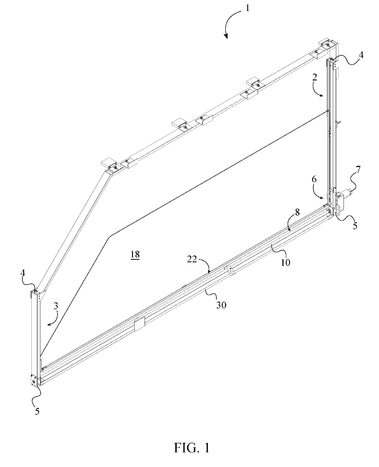
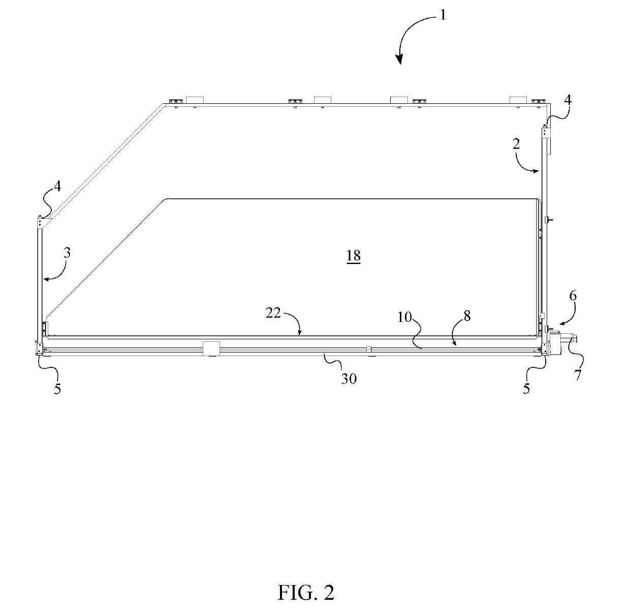
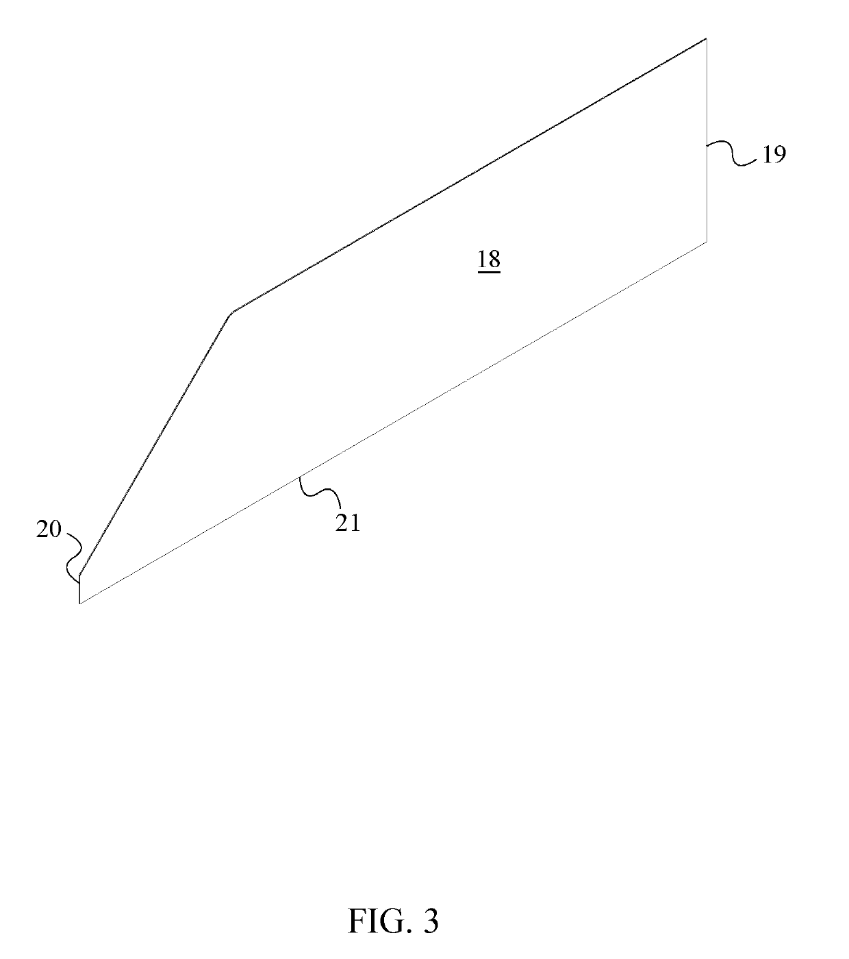
[0020]As seen in FIG. 1 and FIG. 2, to fulfill the intended functionalities, the present invention comprises a shuttle frame 1, a sliding mechanism 6, a window pane 18, and a bottom edge support groove 22. The shuttle frame 1 determines the overall size and shape of the window. Based upon the boat model and the location on the boat where the window pane 18 is being...


PUM


Abstract

An electronically powered window for a watercraft consists of a shuttle frame, a sliding mechanism, a window pane, and a bottom edge support groove. A first lateral support arm and a second lateral support arm of the shuttle frame along with the bottom edge support groove helps position the window pane within the shuttle frame. The sliding mechanism allows the user to position the window pane such that the window is in an open configuration or a closed configuration. To do so, a first lateral edge is slidably positioned along the first lateral support arm. Moreover, a second lateral edge is slidably positioned along the second lateral support arm.

Description

[0001]The current application claims a priority to the U.S. Provisional Patent application Ser. No. 62 / 546,420 filed on Aug. 16, 2017.FIELD OF THE INVENTION[0002]The present invention relates generally to electronically powered windows. More specifically, the present invention is an electronically powered window for a watercraft. By using the present invention, an individual can control the position of the window by simply controlling a switch.BACKGROUND OF THE INVENTION[0003]A boat operator undergoes different weather conditions when boating. Based upon the weather conditions, certain changes need to be made to the boat. As an example, during rainy and windy conditions, the windows of the boat need to be closed. In another instance, during the summer and warm weather conditions, the user may prefer the windows of the boat to be open. Even though existing windows and existing window controlling mechanisms are effective, there are certain drawbacks to these windows and window control...

Claims


Application Information

Patent Timeline
Patent Type & Authority Applications(United States)
IPC IPC(8): E05F15/697E05D15/16
CPCE05F15/697E05D15/165E05Y2900/514B63B2019/0038B63B19/00E05Y2201/656
Inventor FLOE, WAYNE
Owner FLOE WAYNE
Learn More