Control Stick Cap with Retention Features

a technology of control stick and cap, which is applied in the direction of mechanical control devices, manual control with single control member, instruments, etc., can solve the problem of limited range of movemen

Inactive Publication Date: 2019-05-09
SLOTTA MARK
View PDF5 Cites 3 Cited by
  • Summary
  • Abstract
  • Description
  • Claims
  • Application Information

AI Technical Summary

Benefits of technology

[0006]This invention relates to a control stick assembly. The control stick assembly includes a control stick with a body and an extension. The control stick assembly also includes a control stick cap with a recess. The recess includes a first portion and a second portion. A portion of the control stick body is located in the first portion of the recess. Further, the extension is located in the second portion of the recess. The control stick cap is not deformed by the control stick.
[0007]In some embodiments, the second portion of the recess is located farther from an opening in the control stick cap than the first portion of the recess. Also, the control stick enters the control stick cap through the opening. In some embodiments, walls of the recess are engaged with walls of the control stick. In some embodiments, the extension has an extension width and an extension height, and the second portion of the recess has a width that is the same size as the extension width and a height that is the same size as the extension height.
[0008]This invention also relates to a method of attaching a control stick cap to a control stick. The method includes inserting an extension of the control stick into a first portion of a recess of the control stick cap. The method also includes deforming the control stick cap from an original shape. The method includes moving the extension into a second portion of the recess. The method includes moving a portion of a body of the control stick into the first portion of the recess. The method also includes deforming the control stick cap to the original shape.
[0009]In some embodiments, the method also includes providing a control stick cap having the original shape.
[0010]Some embodiments of this invention relate to a method of attaching a control stick cap to a control stick. The method includes providing a control stick having a body and an extension. The extension defines a portion of the control stick which is wider than the body. The method includes providing a control stick cap having a recess with a first portion and a second portion. The first portion of the recess is connected to an opening on an outer surface of the control stick cap. The control stick cap has an original shape. The method includes inserting the extension of the control stick through the opening and into the first portion of the recess. The method includes deforming the control stick cap from the original shape. The method includes moving the extension on the control stick into the second portion of the recess. The method includes moving a portion of the body of the control stick into the first portion of the recess. The method also includes deforming the control stick cap to the original shape.

Problems solved by technology

Control sticks are typically made of plastic or other rigid material and have a limited range of movement.

Method used


Image

  • Control Stick Cap with Retention Features
  • Control Stick Cap with Retention Features
  • Control Stick Cap with Retention Features

Examples


Embodiment Construction

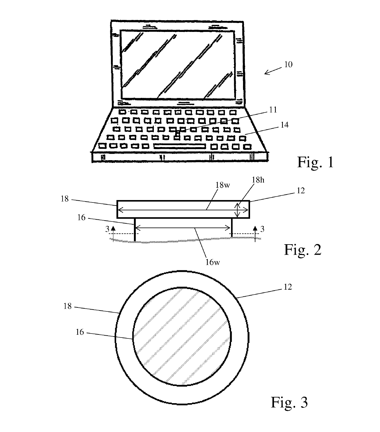
[0025]Referring now to the drawings, there is illustrated in FIG. 1 a laptop computer, indicated generally at 10. The laptop computer includes a control stick assembly 11, which is mounted within a keyboard 14 on the laptop 10. The illustrated laptop 10 is one example of a device on which the control stick assembly 11 may be located. However, the control stick assembly 11 may be mounted on any desired type of device, such as handheld controller.

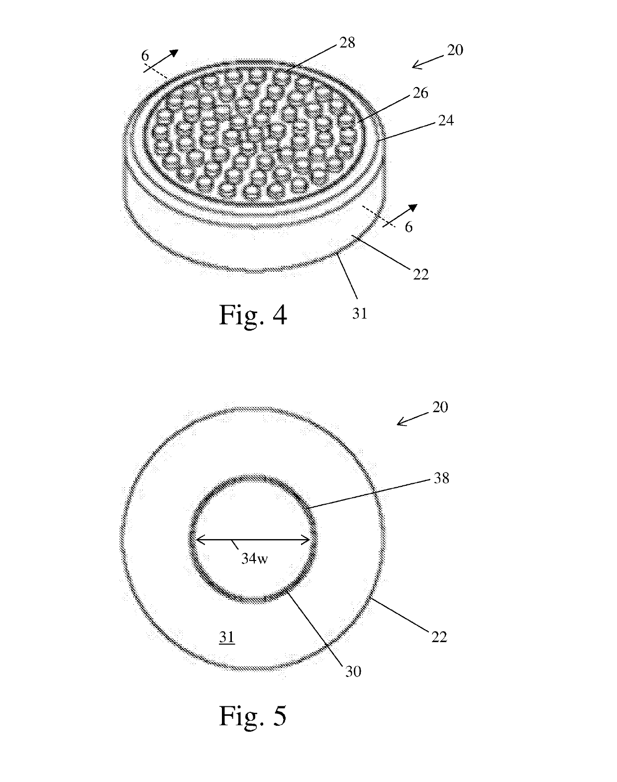
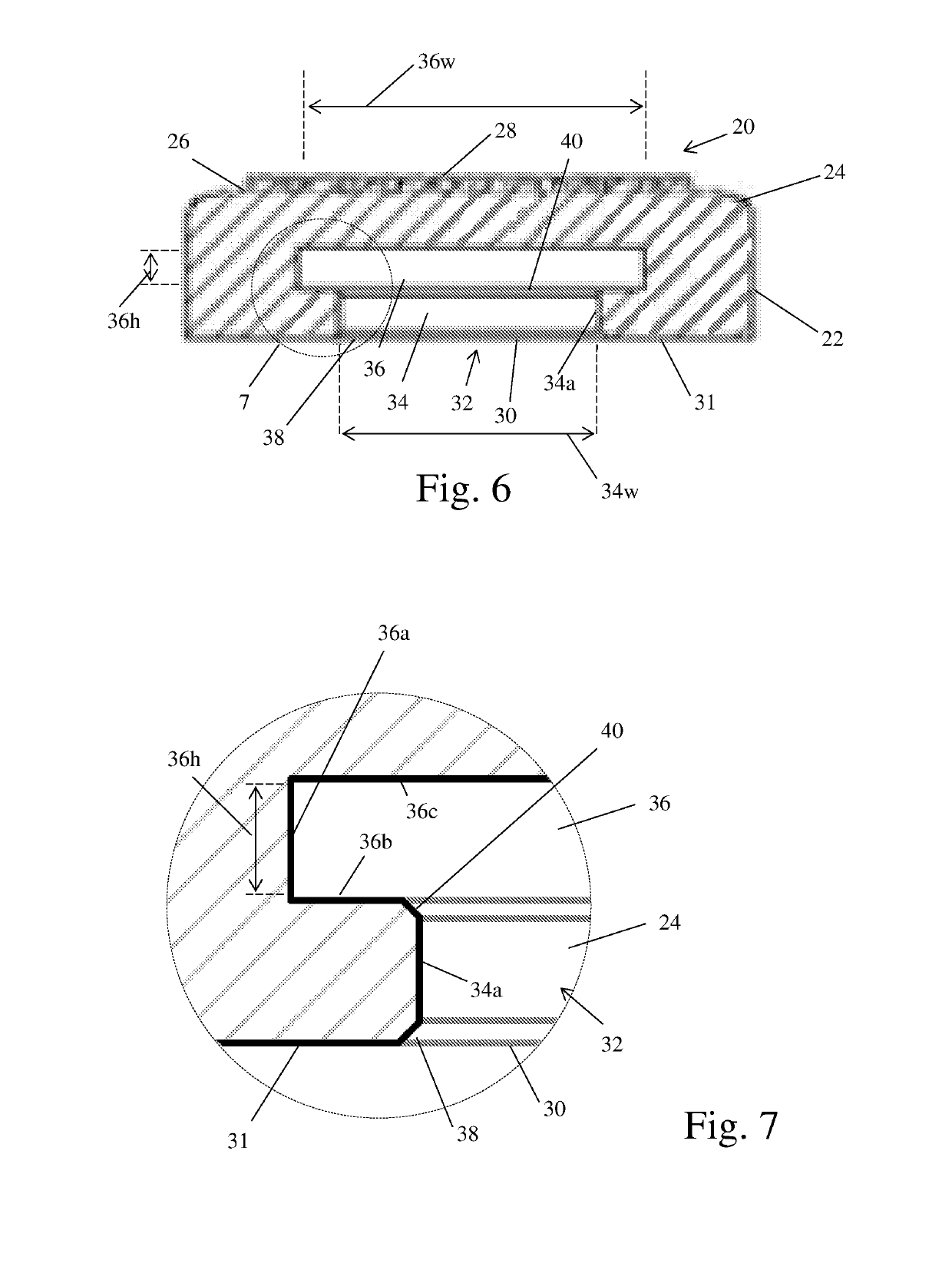
[0026]Referring to FIG. 13, there is shown a cross-sectional view of the control stick assembly 11. The control stick assembly 11 includes a control stick 12 and an attached control stick cap, indicated generally at 20. Referring to FIG. 2, there is shown a side view of the control stick 12. The illustrated control stick 12 is made of plastic, but may be made of any desired material. The control stick 12 includes a body 16 and an extension 18. The extension 18 extends beyond the outline of the body 16 and defines a portion of the control stic...


PUM


Abstract

A control stick assembly includes a control stick with a body and an extension. The control stick assembly also includes a control stick cap with a recess. The recess includes a first portion and a second portion. A portion of the control stick body is located in the first portion of the recess. Further, the extension is located in the second portion of the recess. The control stick cap is not deformed by the control stick.

Description

CROSS-REFERENCE TO RELATED APPLICATIONS[0001]This application claims the benefit of U.S. Provisional Application No. 62 / 321,483, filed Apr. 12, 2016, the disclosure of which is incorporated herein by reference.BACKGROUND OF THE INVENTION[0002]This invention relates in general to a cap for a control stick. More specifically, this invention relates to a cap for a control stick with improved retention features.[0003]Control sticks are often used as user input devices on laptop computers and other devices such as handheld controllers or fixed consoles. One common use for a control stick is as a mouse control device which is located in a central area on a laptop computer keyboard. Control sticks are typically made of plastic or other rigid material and have a limited range of movement. A user may place their finger on the control stick and employ the control stick as a directional input.[0004]In many applications, the control stick includes a cap or cover. The cap is located between the ...

Claims


Application Information

Patent Timeline
Patent Type & Authority Applications(United States)
IPC IPC(8): G05G1/06G05G9/047G06F3/0338
CPCG05G1/06G05G9/047G06F3/0338G06F3/03543
Inventor SLOTTA, MARK
Owner SLOTTA MARK
Why Eureka
Try Eureka