Apparatus and method for comminuting of material

Active Publication Date: 2019-04-25
TEVO
View PDF8 Cites 1 Cited by
  • Summary
  • Abstract
  • Description
  • Claims
  • Application Information

AI Technical Summary

Benefits of technology

The invention is a new way to position conveyor surfaces in a way that allows for precise crushing of solid materials. This results in a high-quality, low-energy consumption end product that can be easily divided into different particle sizes. The technical effects of this invention include improved efficiency, product quality, and better device design.

Problems solved by technology

The noteworthy issue is that comminuting material is the biggest energy-consuming process of these industrial sectors.
Friction and the heat it causes takes up most of the energy consumption in comminuting.
The main part of the amount of energy required is used at the grinding stages, the costs of which in a mineral concentration process may be up to 70% of the concentration costs.
There are, however, problems associated with the prior art methods.
The problem with the prior art methods and apparatuses is their high energy consumption and modest efficiency.
A further problem is the low quality of the end product, that is, the fine particles, due to the breaking manner of the particles based on fast compression, which leads to arbitrary fracture planes in the area of principal stress fields, and the formation of a hyperfine fraction which is difficult to process.

Method used


Image

  • Apparatus and method for comminuting of material
  • Apparatus and method for comminuting of material
  • Apparatus and method for comminuting of material

Examples


Embodiment Construction

[0016]The invention relates to comminuting of material by compression, by way of example in particular to comminuting of elastoplastic material. Minerals, for example, serve as an example of a comminutable, at least partly elastoplastic material. If the material is homogeneous and fully elastic, the stress field formed in the material is distributed according to the location of the compression points and surface area in the material, and the stress field may be calculated relatively accurately based on the bond strength between atoms. In practise, all the comminutable material particles are non-homogeneous and at least slightly plastic, and they typically include a plurality of matter components unevenly distributed in the material and which have discontinuity points and micro-cracks at their boundary surfaces, in particular. In addition to minerals, ceramic material and glass are elastoplastic material.

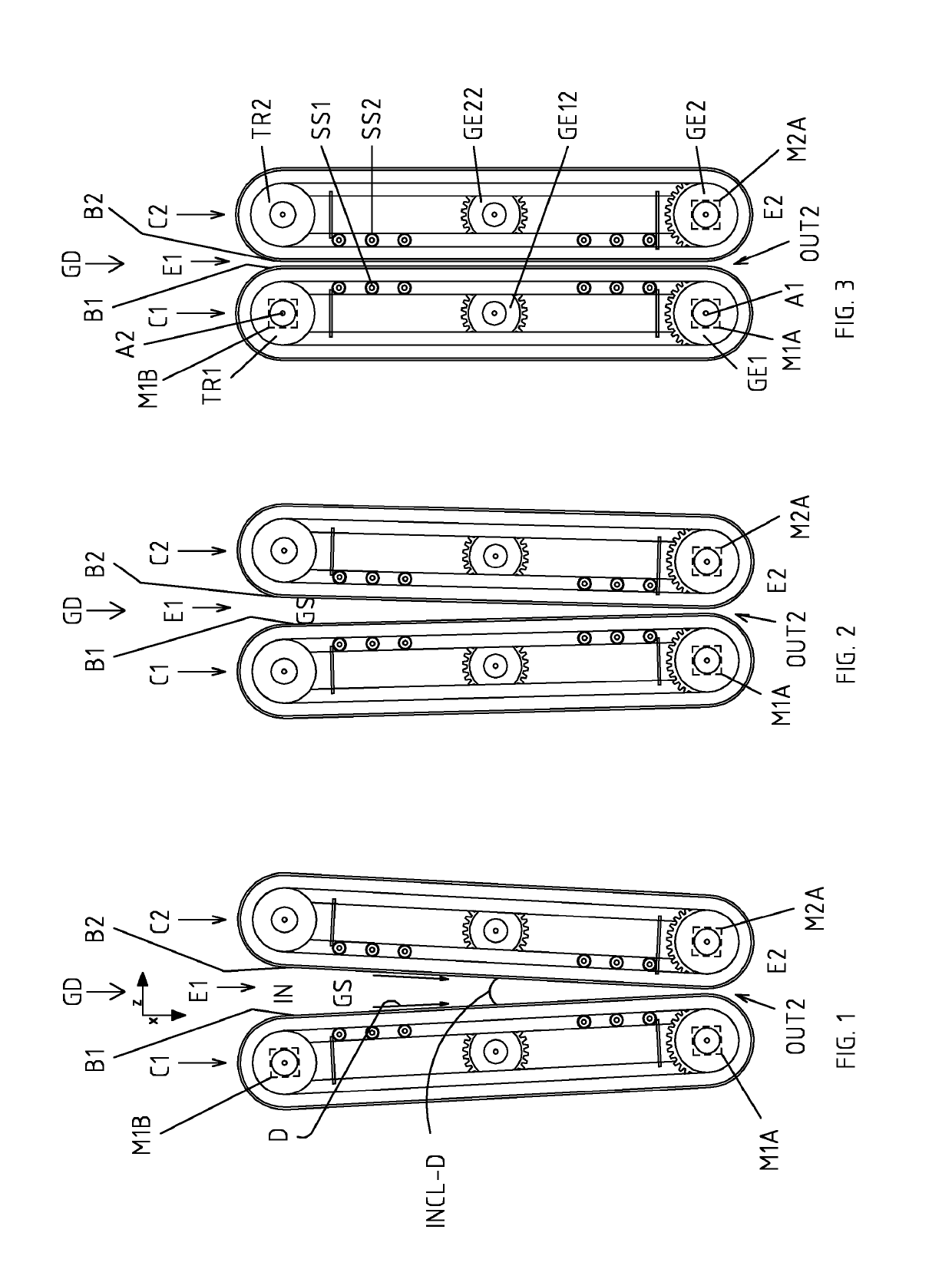
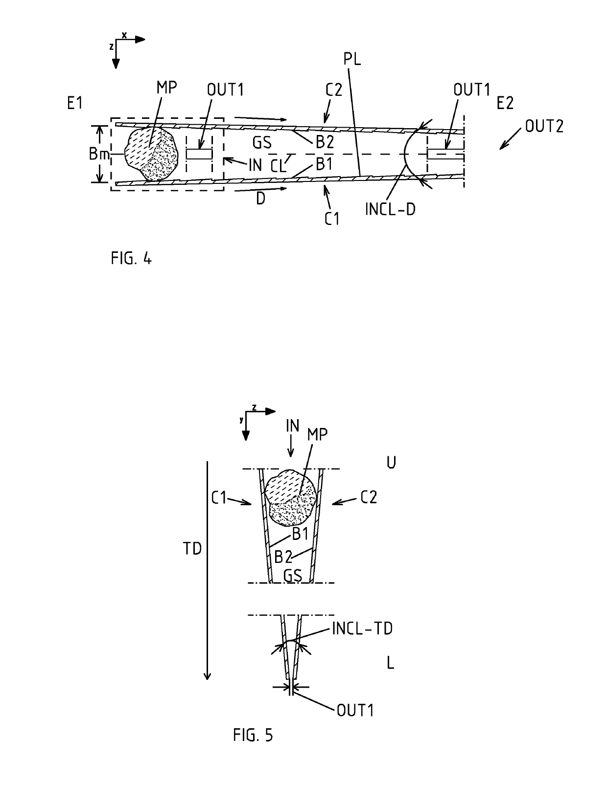
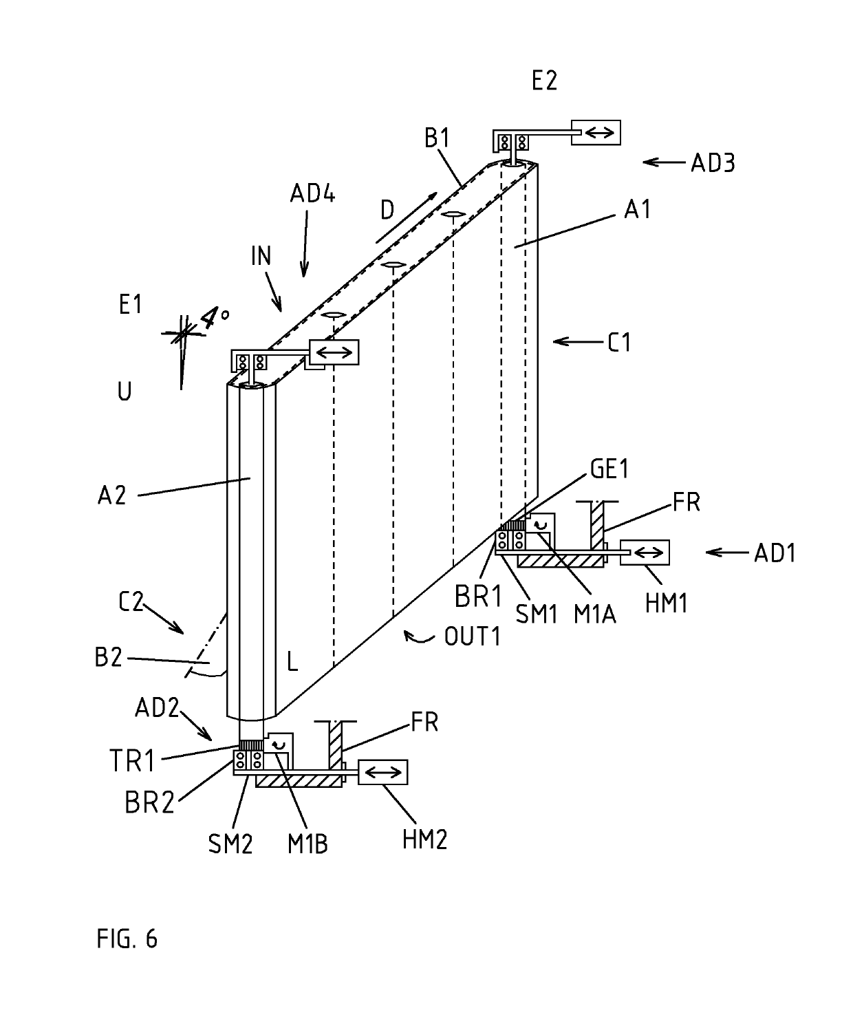
[0017]The apparatus GD shown in the figures comprises a first conveyor structure...


PUM


Abstract

The invention relates to an apparatus for comminuting of material The apparatus comprises a first conveyor structure (CI) with a first conveyor surface (B1), a second conveyor structure (C2) with a second conveyor surface, and in which apparatus the first conveyor surface (B1) and the second conveyor surface (B2) are set facing each other. The conveyor surfaces (B1, B2) are arranged to define a comminuting space (GS) in the apparatus, The apparatus has means (MIA, M2A) for bringing the conveyor surfaces in a movement in the direction of movement D where the two conveyor surfaces (B1, B2) placed to face each other are arranged to move from a first end (E1) of the conveyor structures towards a second end (E2) of the conveyor structures. The conveyor surfaces positioned to face each other are placed in a convergent manner so that the gap between the conveyor surfaces (B1, B2) narrows when examined in the movement direction (D) of the conveyor surfaces, so that the advancing movement of the conveyor surfaces is arranged to bring about compression in the material being comminuted. In the invention, the conveyor surfaces (B1, B2) are in a double-converging manner so that in addition to said convergence in the movement direction, the conveyor surfaces are additionally placed in a convergent manner so that the gap between the conveyor surfaces (B1, B2) also narrows in the transverse direction (TD) in relation to the movement direction, said comminuting space (GS) thus becoming double-converging.

Description

BACKGROUND OF THE INVENTION[0001]There exists a great need for comminuting of material in the mining, mineral, and cement industries. The noteworthy issue is that comminuting material is the biggest energy-consuming process of these industrial sectors.[0002]The energy consumption required by the comminuting process depends on the material type and its magnitude is typically 20-60 kWh / t, but in fine comminuting may be as much as 100-1000 kWh / t.[0003]Friction and the heat it causes takes up most of the energy consumption in comminuting. The main part of the amount of energy required is used at the grinding stages, the costs of which in a mineral concentration process may be up to 70% of the concentration costs.[0004]Some of the prior art apparatuses and methods are disclosed in publications U.S. Pat. Nos. 2,981,486, 1,704,823 and GB709729.[0005]There are, however, problems associated with the prior art methods. The problem with the prior art methods and apparatuses is their high energ...

Claims


Application Information

Patent Timeline
IPC IPC(8): B02C19/00
CPCB02C19/0006B02C1/06B02C18/00B02C19/00B02C1/02B02C1/10B02C18/0076
Inventor KUOPANPORTTI, HANNUHYNYNEN, ILKKA
Owner TEVO
Why Eureka
Try Eureka