
Detachable surface mounting utility hub

a utility hub and surface mount technology, applied in electric vehicles, electric power, transportation and packaging, etc., can solve the problems of slow charging, inconvenient and expensive to carry a large number of batteries, and inability to produce enough electricity for more than one device,

Active Publication Date: 2019-02-28
SOUTONO LLC
View PDF29 Cites 2 Cited by
  • Summary
  • Abstract
  • Description
  • Claims
  • Application Information

AI Technical Summary

Benefits of technology

The patent describes a detachable surface mounting utility hub that allows for easy access to solar-generated electricity inside structures or tents. The hub is mounted on the interior walls or roof of a structure and connects to a solar panel that is mounted on the exterior. The hub is convenient and easy to access, and it occupies minimal space within the structure. The hub is ideal for outdoor and tenting usage. The technical effect of this invention is to provide a convenient and easy to access way to use solar-generated electricity inside structures or tents.

Problems solved by technology

Even though many of the devices and applications have batteries that allow the devices to go wherever we go or to use the applications wherever we go, without a replenishing power source, these devices and applications eventually become unusable.
However, it is inconvenient and expensive to carry a large number of batteries when camping, traveling long distances, traveling to remote locations, or outdoors for extended periods of time.
However, portable solar panels lack the surface area to produce sufficient electricity for more than one device and provide slow charging.
Solar panels also have to be used outside where they can be exposed to light, which can be inconvenient or inaccessible when wanting to use or recharge devices or applications inside a structure.

Method used


Image

  • Detachable surface mounting utility hub
  • Detachable surface mounting utility hub
  • Detachable surface mounting utility hub

Examples


Embodiment Construction

[0017]A detachable surface mounting utility hub is disclosed. The utility hub mounts on the interior or inside of walls or roof of a structure and connects to a power source such as a solar panel that is mounted on the exterior or outside of the structure. The utility hub distributes power from the power source to various devices or applications inside the structure in a convenient and easy to access manner that involves minimal setup. the utility hub occupies minimal space within the structure and remains out of the way while still being easy to access by virtue of mounting to the structure's interior walls or roof. Accordingly, the utility hub is ideal for outdoor and tenting usage.

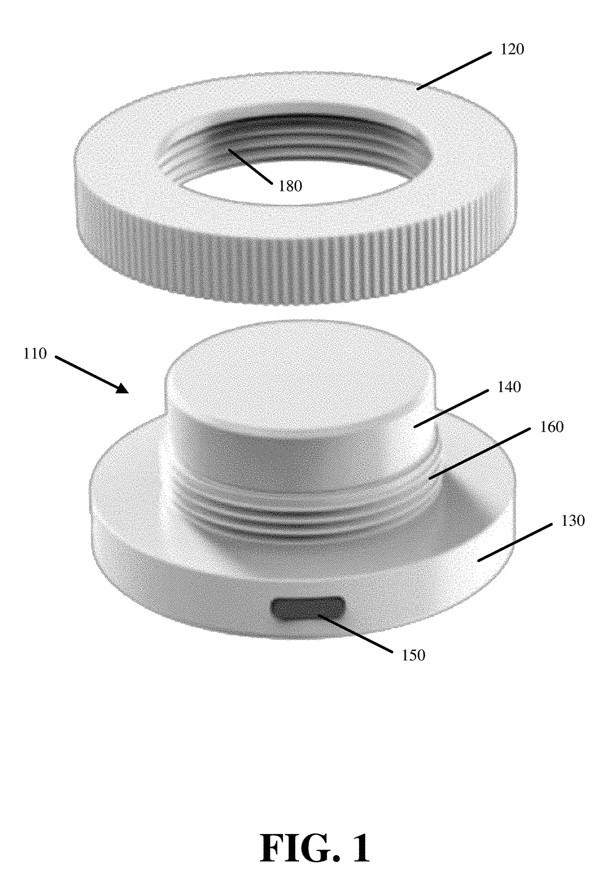
[0018]FIG. 1 illustrates a separated view of the utility hub of some embodiments. The utility hub has two primary structures. The first structure is a power distribution body 110. The second structure is an attachment ring 120.

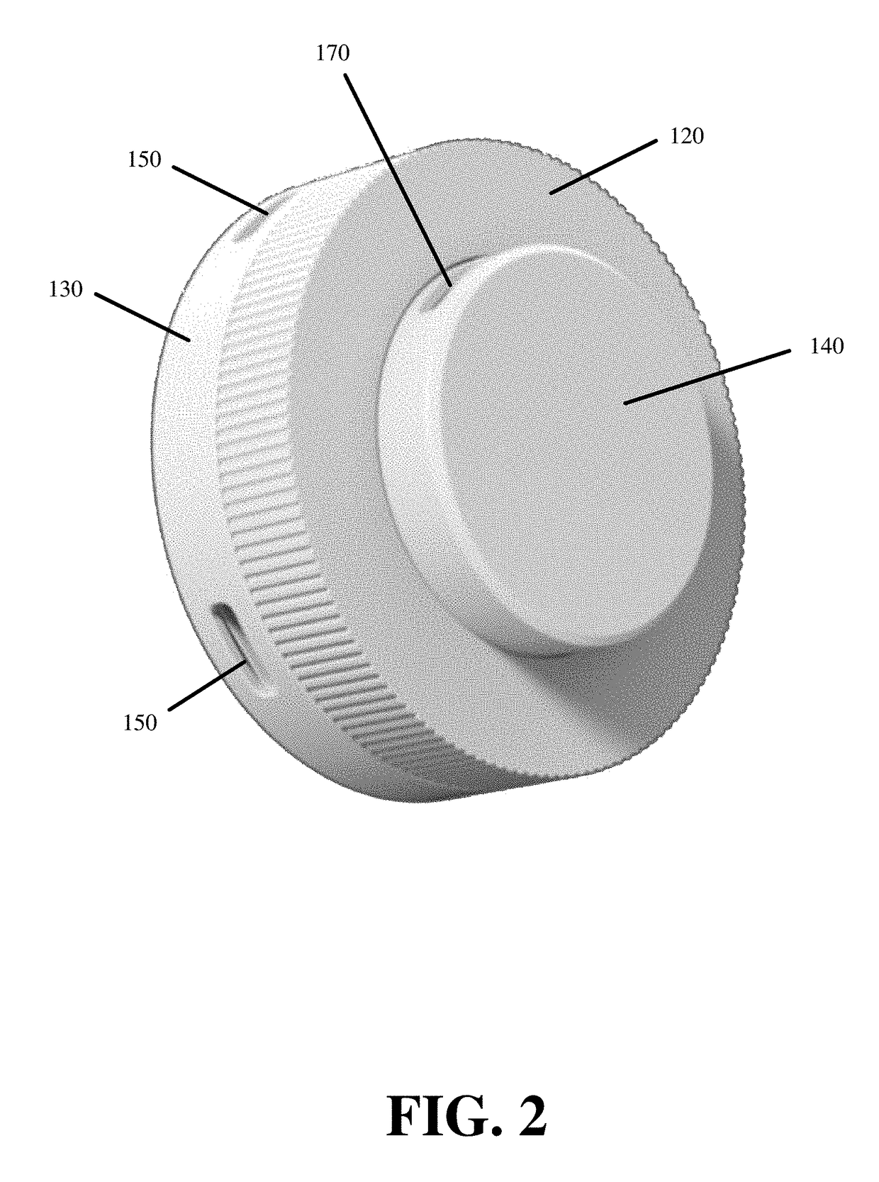
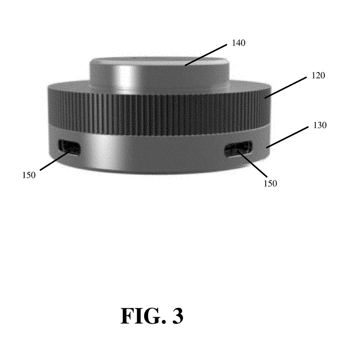
[0019]FIGS. 2 and 3 illustrate a coupled view of the utility hub of some embo...


PUM


Abstract

Disclosed is a hub for charging and other applications when camping or away from power infrastructure. The hub mounts on an elevated surface such as a structure wall or roof to remain out of the way but still accessible. The hub has a body and an attachment ring. The body has a cylindrical column of a first diameter and a base of a greater second diameter. The cylindrical column has an input port along top and exterior threading below the input port. The elongated base has an output port along a bottom. The input port connects to a power source, such as a solar panel, and feeds current to the output port. The cylindrical column passes through an opening of a structure and the attachment ring screws onto the threading exposed on the other side of the structure, thereby attached the hub to the structure.

Description

BACKGROUND ART[0001]Electricity drives most of the tools and applications we use in our daily lives. We depend on electricity for communication, lighting, work, entertainment, and other applications.[0002]Even though many of the devices and applications have batteries that allow the devices to go wherever we go or to use the applications wherever we go, without a replenishing power source, these devices and applications eventually become unusable. Some devices or applications allow for the swapping of depleted batteries with fresh batteries. However, it is inconvenient and expensive to carry a large number of batteries when camping, traveling long distances, traveling to remote locations, or outdoors for extended periods of time.[0003]Renewable energy sources can power devices or recharge depleted batteries. Portable solar panels are one such renewable energy source that can be carried on backpacks or on one's person. However, portable solar panels lack the surface area to produce s...

Claims


Application Information

Patent Timeline
IPC IPC(8): H02J7/35
CPCH02J7/355H02J7/35H02J50/10H02J7/342H02J7/00H02J7/0042H02J7/0044
Inventor CANO, JOSE ENRIQUE PACHECOSUNDERMEYER, JOHNSMITH-KIELLAND, INGVALDLEE, JU CHIA
Owner SOUTONO LLC
Learn More