
System and device for improved ultrasound cavitation mapping

Active Publication Date: 2019-01-10
THE BOARD OF TRUSTEES OF THE LELAND STANFORD JUNIOR UNIV
View PDF1 Cites 2 Cited by
  • Summary
  • Abstract
  • Description
  • Claims
  • Application Information

AI Technical Summary

Benefits of technology

The invention includes a computer system that can detect and eliminate spurious cavitation signals in a liquid. It uses a modified parabola to fit the signals and calculates the lifetime of each bubble. By eliminating signals with negative lifetimes, the system can improve the accuracy of the measurements.

Problems solved by technology

However, these active imaging methods are incapable of monitoring short-lived transient bubbles that undergo inertial cavitation.
Although ultrafast B-mode imaging has been shown to overcome this challenge by using frame rates higher than typical B-mode imaging, these methods, while providing information about the existence and location of bubbles, are unable to provide information that is useful for classifying stable / inertial cavitation.
Moreover, such active cavitation imaging methods typically record echo signals when the therapeutic transducer is not transmitting, because the imaging pulses interfere with the acoustic emissions from the bubbles.
However, these passive cavitation detection methods typically use a single element transducer that does not provide localized spatial information of cavitation, but rather cavitation signals spatially averaged within the focal volume.
However, these TEA algorithms suffer from poor axial resolution due to a combination of the limited point spread function of the array transducer and bubble-bubble interactions.
The Capon beamformer, despite its promise for PCM, has several limitations.
First, this beamformer requires high signal-to-noise ratio (SNR) to achieve the desired resolution, and reverts back to the delay-and-sum beamformer when the SNR is low.
While promising results have been shown in phantoms and small animals, translation to human imaging with this technique will be difficult due to the presence of inhomogeneous tissue that decrease SNR from reverberation clutter and phase aberration.
In addition, the technique minimizes the output power of the array for non-ideal signals rather than improving localization of the cavitation signals, thereby eliminating potential cavitation signals not occurring on the beamforming axis, such as cavitation signals due to sidelobes.

Method used


Image

  • System and device for improved ultrasound cavitation mapping
  • System and device for improved ultrasound cavitation mapping
  • System and device for improved ultrasound cavitation mapping

Examples


Embodiment Construction

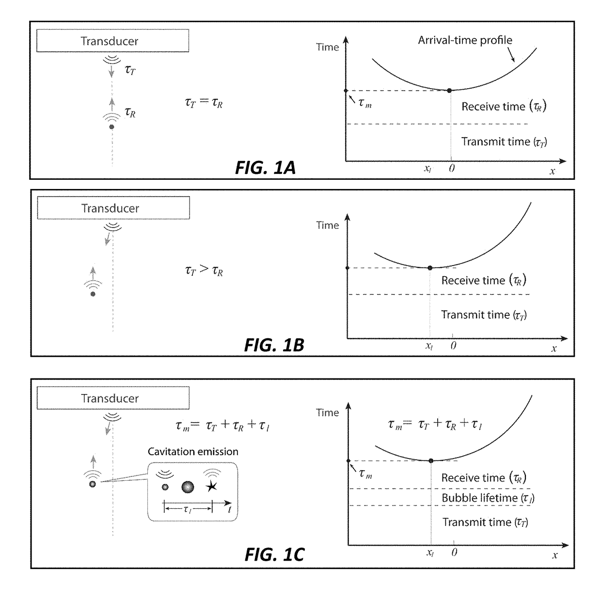
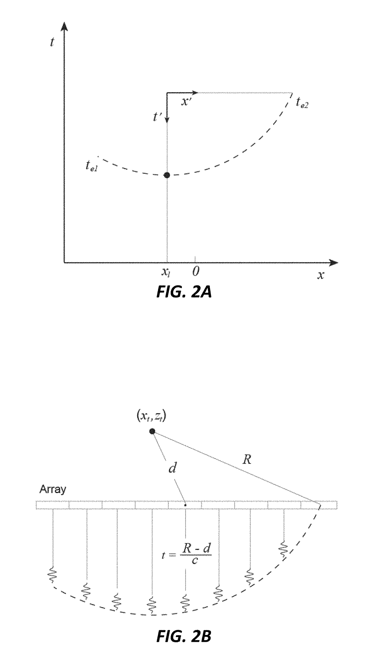
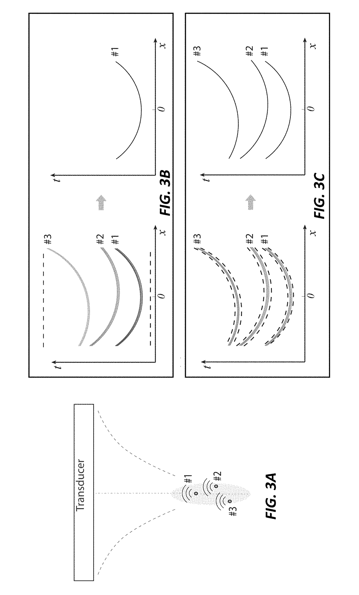
[0024]Disclosed herein is a method to adapt a speed of sound estimation technique to perform passive cavitation mapping based on cavitation source localization. The axial resolution of passive cavitation imaging by source localization is significantly improved by eliminating factors contributing to the tail artifact. According to the invention, cavitation sources are localized by applying a polynomial fit to arrival-time profiles of the cavitation signals, which is not limited by the axially-elongated point spread function of the passive imaging transducer. Furthermore, the tail artifact arising from bubble-bubble interactions can be effectively suppressed based on analysis on fitting quality and bubble lifetime, thus further improving the imaging quality.

[0025]Upon insonification with an imaging pulse, an ideal stationary point target reflects a spherical wave. The arrival times of the backscattered echoes as they return to a linear array of transducer elements are based on the pat...


PUM


Abstract

A passive cavitation mapping method is provided that includes capturing a channel signal from at least one ultrasound transducer in an array of ultrasound transducers, isolating a cavitation signal in the channel signal, time-gating the channel signal about the cavitation signal, computing a time-delay between neighboring the cavitation signals in adjacent the channel signals, computing a modified parabolic fit to the square of the arrival times, where the modified parabolic fit includes a coordinate transformation using an x location of a leading edge of wavefronts of the cavitation signal and a maximum arrival time of the cavitation signal, extracting a location of a cavitation signal source at point (x, z) in the coordinate transformation, computing a cavitation magnitude for each non-eliminated cavitation signal, creating a passive cavitation map by convolving the cavitation magnitude and the source location with an uncertainty function, and using the cavitation map for therapeutic ultrasound applications.

Description

CROSS-REFERENCE TO RELATED APPLICATIONS[0001]This application claims priority from U.S. Provisional Patent Application 62 / 529,414 filed Jul. 6, 2017, which is incorporated herein by reference.STATEMENT OF GOVERNMENT SPONSORED SUPPORT[0002]This invention was made with Government support under contract EB022298 awarded by the National Institutes of Health. The Government has certain rights in the invention.FIELD OF THE INVENTION[0003]The present invention relates generally to ultrasound cavitation mapping. More particularly, the invention relates to a method of passively listening to a cavitation event, where there is no timing associated with the event, where the received signal is processed using a modified parabolic fit algorithm to determine the location of the event.BACKGROUND OF THE INVENTION[0004]Cavitating bubbles can produce localized mechanical effects, making them useful for various ultrasound-based applications ranging from sonoporation-induced drug delivery and blood-brai...

Claims


Application Information

Patent Timeline
IPC IPC(8): A61N7/00A61B8/08
CPCA61N7/00A61N2007/0039A61B8/5269A61B8/5207A61B2017/00106A61N2007/0065A61N2007/0095A61B8/085A61B8/481
Inventor LEE, TAEHWAWILLMANN, JUERGEN K.DAHL, JEREMY JOSEPH
Owner THE BOARD OF TRUSTEES OF THE LELAND STANFORD JUNIOR UNIV
Learn More