
Aspherical dome display and method of rear projection

a dome display and dome technology, applied in the field of non-spherical projection displays, can solve the problems of low resolution system, affecting pilot ergonomics, and affecting the pilot's vision

Active Publication Date: 2018-12-20
TREALITY SVS BELGIUM BV
View PDF0 Cites 2 Cited by
  • Summary
  • Abstract
  • Description
  • Claims
  • Application Information

AI Technical Summary

Benefits of technology

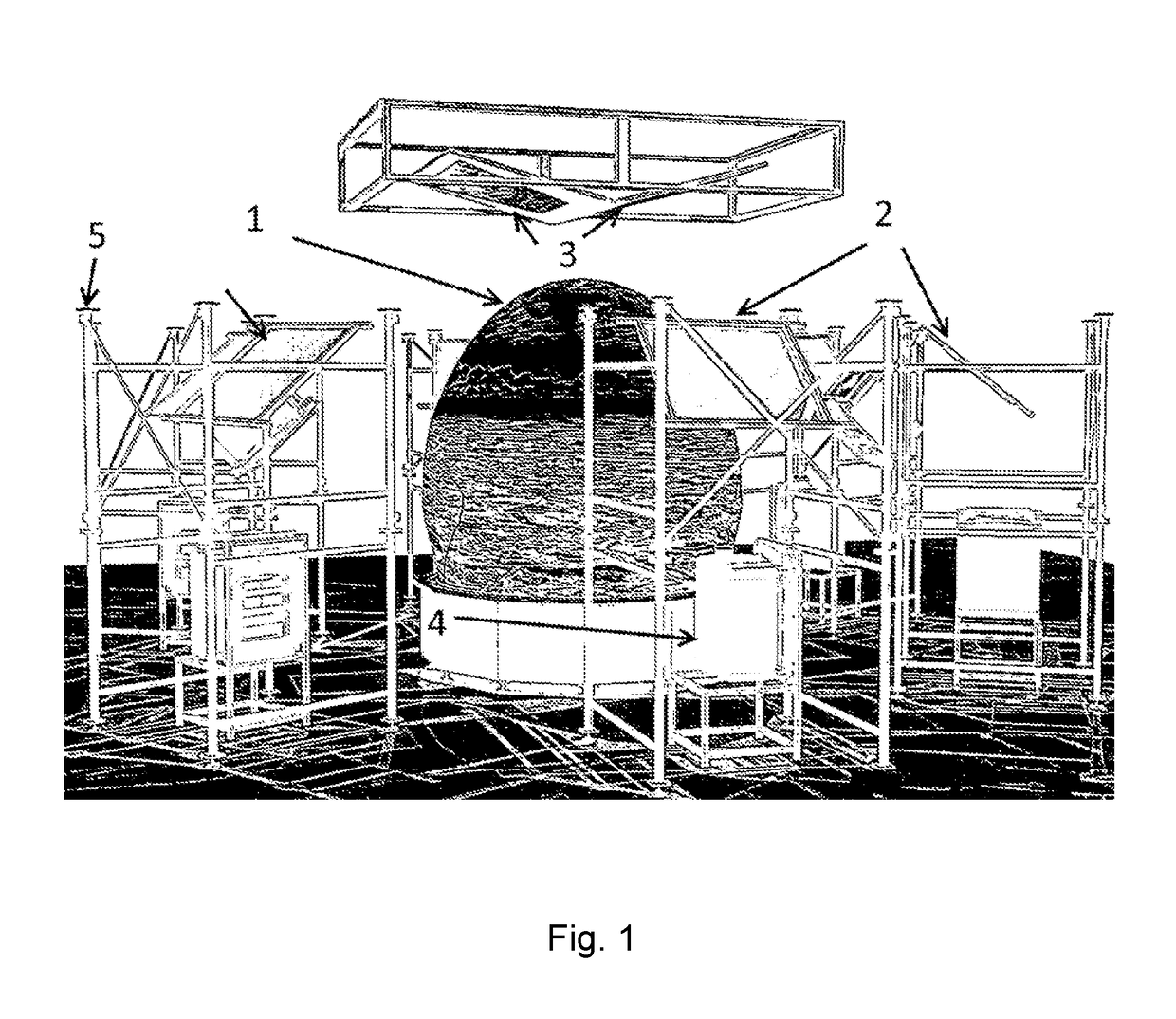
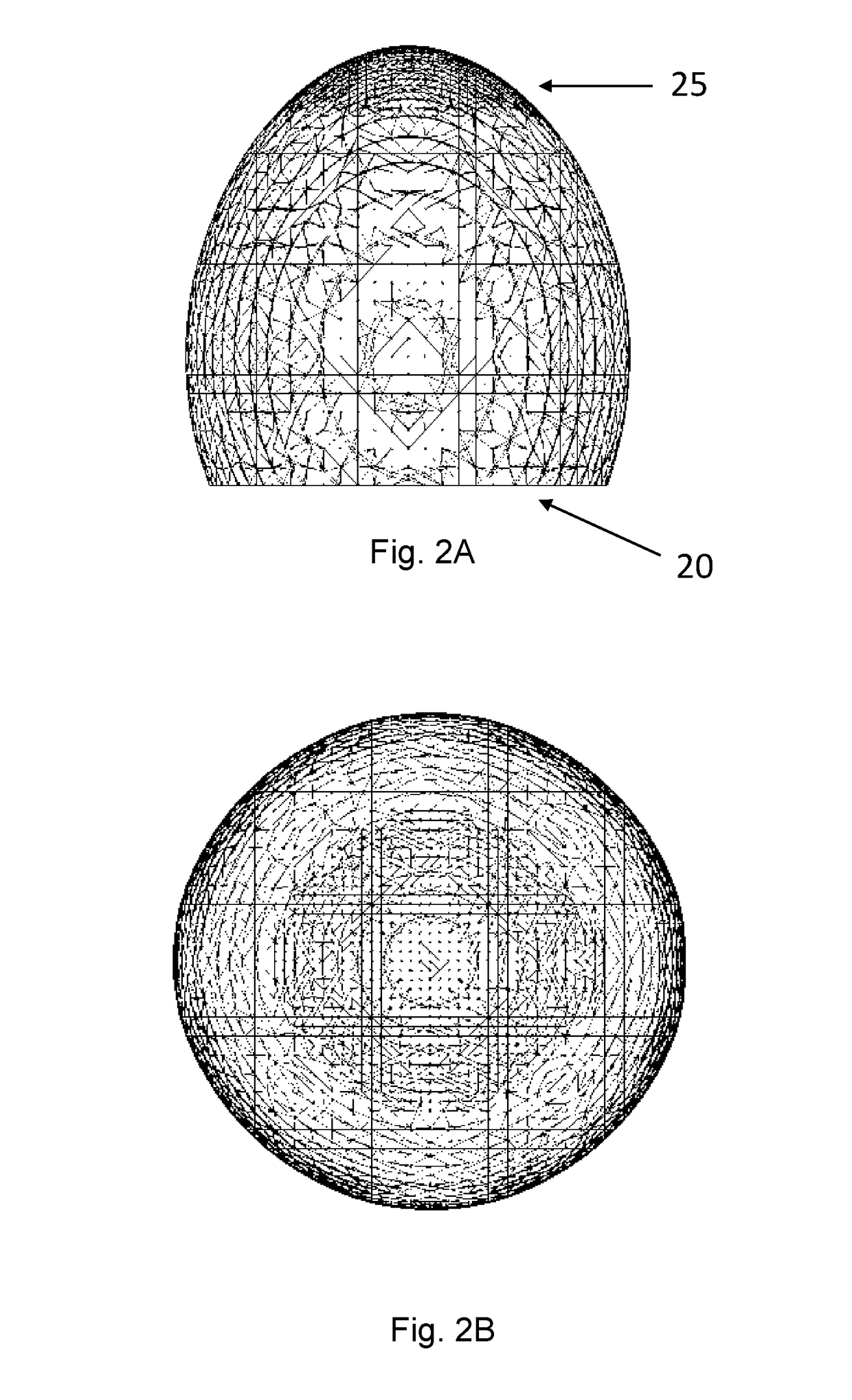
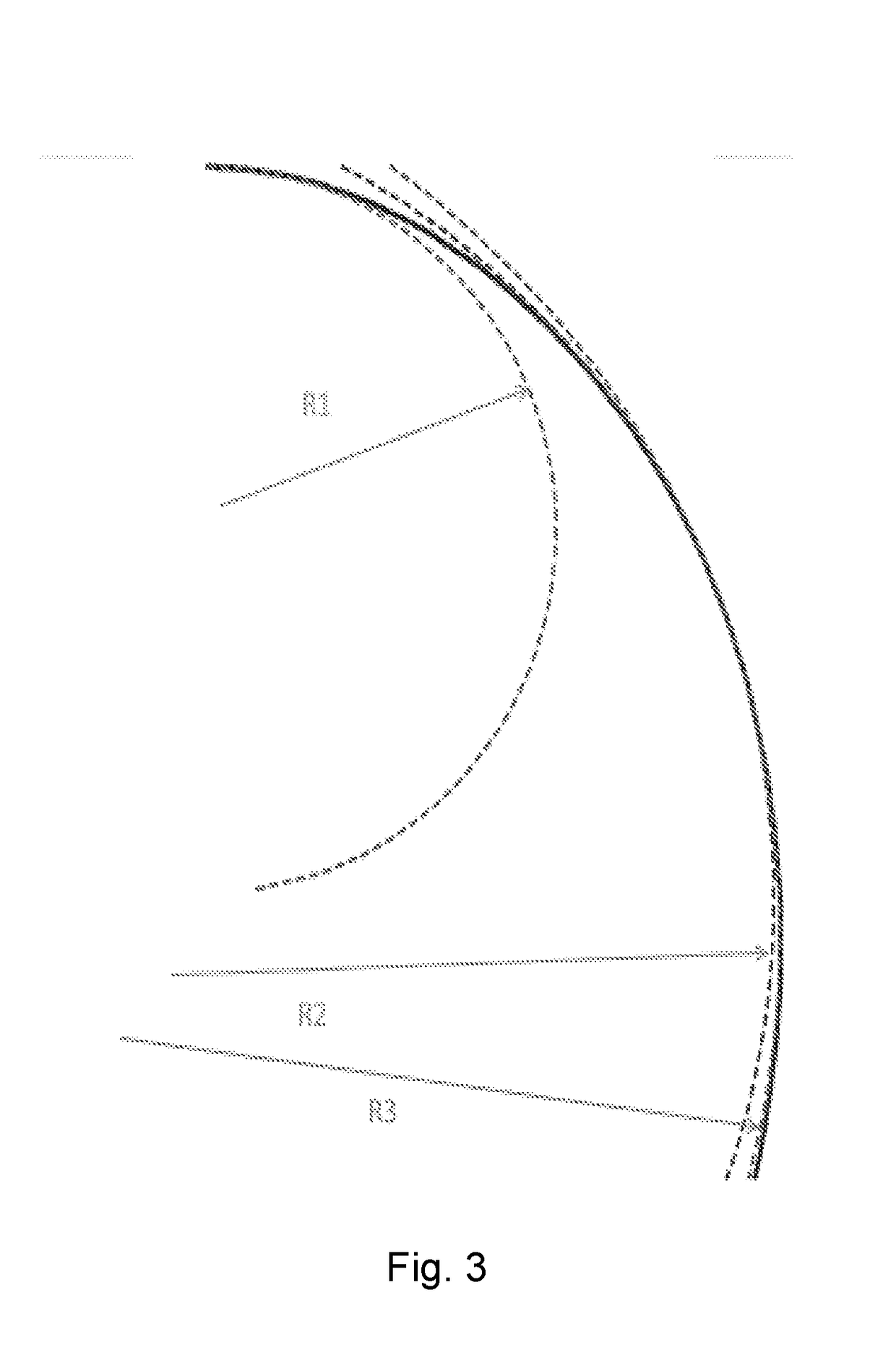
The patent describes a non-spherical display screen system for a widescreen projector that is designed to improve the viewing experience for the viewer. The screen has a non-symmetrical shape with an axis of revolution that is perpendicular to the horizontal plane and forms a solid of revolution around it. The screen has a thickness and is made up of a first layer and a second diffusing layer. The system includes a rear projected display screen structure that has a screen surface with a thickness. The non-symmetrical shape of the screen is optimized for the viewer's ergonomics. The system also includes a first group of projectors and a second group of projectors to provide a combined image with a horizontal field of view of at least 180° and a vertical field of view in the range of at least 20° upward. The system can have but-matched projectors with a geometry accuracy of better than 10 arc minutes. The screen can be designed to have a minimum radius of curvature R1 and a maximum radius of curvature R2, with R2 diffusing the light beams. The technical effects of this patent include improved viewing experience for the viewer, optimized for ergonomics, and a wide field of view for the viewer.

Problems solved by technology

The advantage of front projected systems is that they have a compact footprint but their projector placement is complex and widescreen projectors are used in a less optimal way resulting in systems with a lower resolution.
Widescreen projectors with aspect ratios of more than 1.34 typically cannot be matched very optimally with a spherical screen resulting in a lot of loss of pixels and brightness.
The drawback is the visual ergonomics for the pilots are strongly compromised as the distance between the pilot's eyes and the screen is no longer constant, changes in a non-constant way at the facet edges and is dependent of the angle at which the pilot looks at the screen.

Method used


Image

  • Aspherical dome display and method of rear projection
  • Aspherical dome display and method of rear projection
  • Aspherical dome display and method of rear projection

Examples


example

[0155]For λ=550 nm, m=80 and F / 2.5 we have a coherence width of 220 μm; (θ′≈2.5·10−3 rad)

[0156]A diffuser layer with scattering cone angle 140° has a coherence area with diameter ≈0.59 μm.

[0157]The eye has a resolving power of approximately 1 arc-minute=0.29·10−3 rad and has a resolution cell of diameter ≈436 μm at a viewing distance of 1.5 m. The number of statistically independent coherence areas in an eye resolution spot is in this case approximately 500·103. The speckle noise will be effectively reduced by this diffuser. (“Speckle-free rear-projection screen using two close screens in slow relative motion”, E. Rowson, A. Nafarrate, R. Norton, J. Goodman, J. Opt. Soc. Am. Vol. 66, No. 11, November 1976).

[0158]In accordance with an aspect of the present invention a tinted inner layer (α, t) with scattering particles (d, c, Δn, n1


PUM


Abstract

A non-spherical projection display structure and system that can be optimized for the ergonomics of preferably one viewer inside the display structure or system. The structure or system is preferably for use with widescreen projectors. The non-spherical projection display structure and system creates a visual projection display and method of operating the display that has a wide horizontal and vertical field of view and uses a rear projected display structure having a projection screen surface with a thickness. The display structure has at least one section with a monotonically increasing or decreasing radius of curvature.

Description

FIELD OF THE INVENTION[0001]The present invention pertains to the field of non-spherical projection displays having a wide horizontal and vertical field of view, the displays being for use with rear projection devices.BACKGROUND[0002]Immersive visual systems are widely used in simulation applications to create out of the window images for pilots or drivers or to create visually surrounding virtual images for one or multiple users.[0003]Currently, there are four main techniques to create large field of view immersive visual display systems.[0004]The first known technique to generate an immersive visual display system with a large field of view is by projecting, with a plurality of projectors, on the front of a spherical surface. The advantage of front projected systems is that they have a compact footprint but their projector placement is complex and widescreen projectors are used in a less optimal way resulting in systems with a lower resolution. Pilots viewing from inside the spher...

Claims


Application Information

Patent Timeline
Patent Type & Authority Applications(United States)
IPC IPC(8): G02B17/06G03B37/04G09B9/30G09B9/32G02B13/06G03B21/56G06T3/00
CPCG02B17/061G03B37/04G09B9/302G06T3/0018G02B13/06G03B21/56G09B9/32G03B21/62G06T3/047
Inventor DE MEERLEER, PETER
Owner TREALITY SVS BELGIUM BV
Learn More