Shield for air-based fryer apparatus
a fryer and air technology, applied in the field of shields for air-based fryer apparatus, can solve the problems of affecting the cooking process, not always practical, and sometimes generating fumes during the cooking process
- Summary
- Abstract
- Description
- Claims
- Application Information
AI Technical Summary
Benefits of technology
Problems solved by technology
Method used
Image
Examples
first embodiment
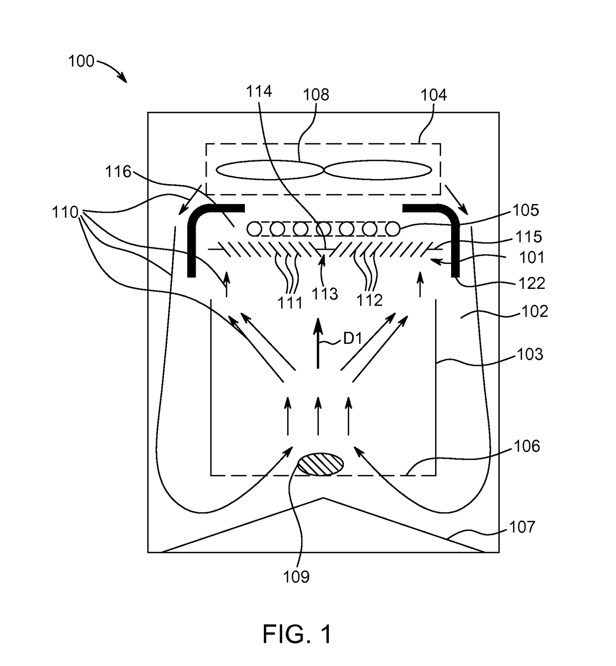
[0050]FIG. 1 illustrates a shield 101 according to the invention in use with a food cooking apparatus 100.
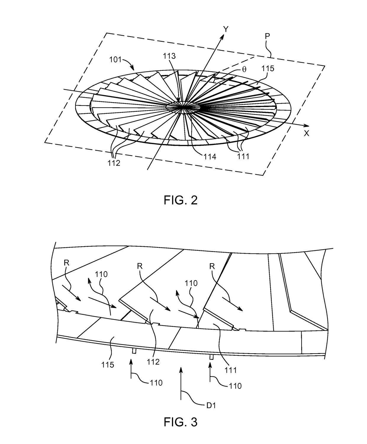
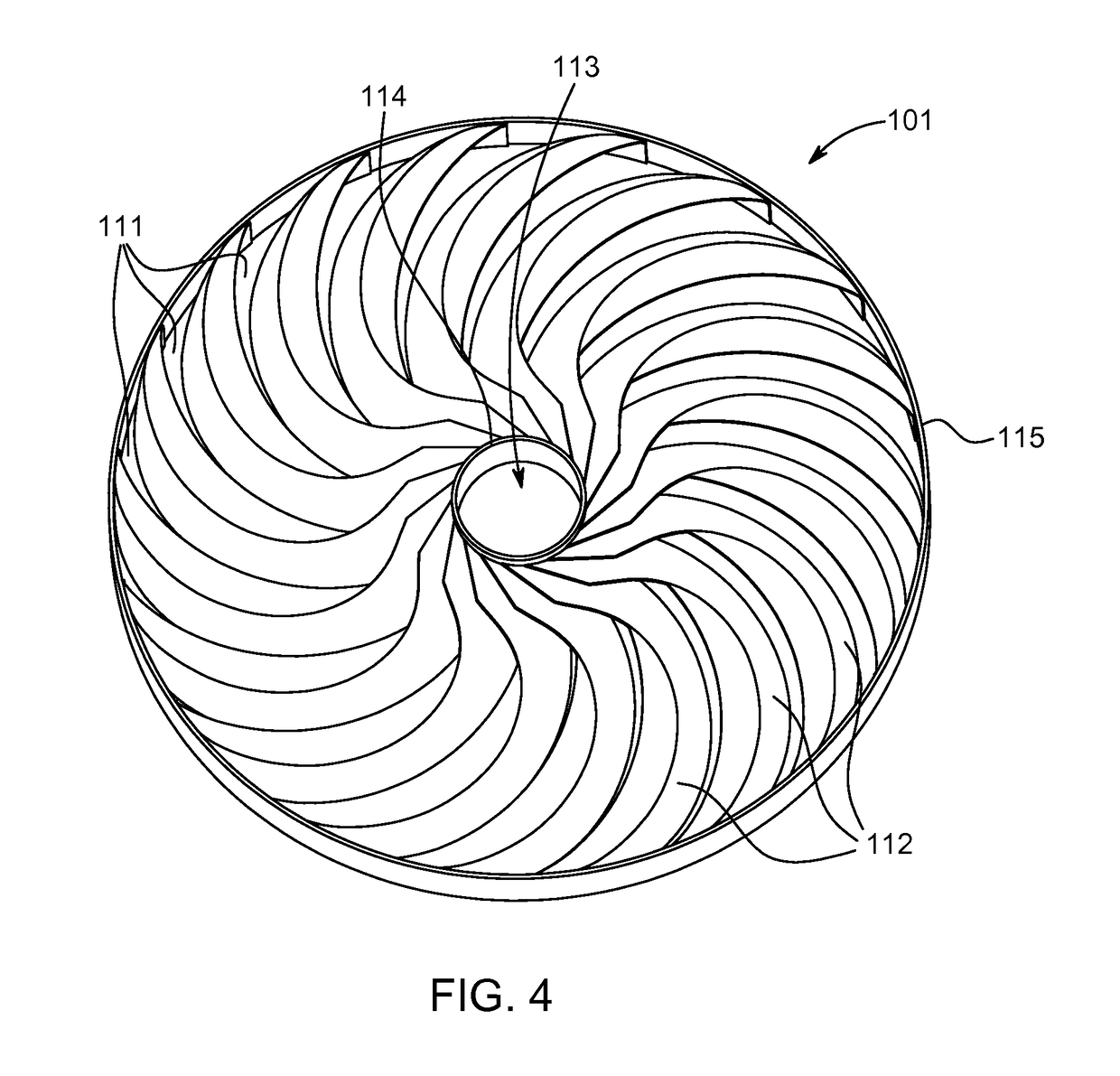
[0051]The present invention provides a shield 101 for use in a cooking apparatus 100 having a food preparation chamber 102 to receive a food support 103, a system 104 for circulating a flow of hot air inside the food preparation chamber 102 and a heating element 105 adjacent the food support 103. The shield 101 is configured to be disposed between the heating element 105 and the food support 103. The shield 101 comprises a plurality of inclined surfaces 112. The shield further comprises a plurality of apertures 111 between the inclined surfaces 112 through which the flow of hot air can pass.
[0052]In particular, the cooking apparatus 100 corresponds to an air-based fryer apparatus using circulation of hot air to cook food ingredients. Alternatively, a circulation of hot air mixed with liquid / water / moisture / steam could also be performed similarly.
[0053]The cooking apparatus 100 co...
fourth embodiment
[0063]FIG. 6 shows a shield 101 of a fourth exemplary embodiment of the invention, including a central portion 113 and an outer ring 115. Three ribs 119 extend radially from the central portion 113 to the outer rib 115. A plurality of curved and angled blades 112 extend concentrically between the ribs 119. The blades 112 serve to at least partially block a direct line of sight in a vertical direction D1 through the apertures 111, and to deflect at least some of the upward vertical flow of hot air 110 through the apertures 111. For example, the shield 101 may entirely block a direct line of sight in a vertical direction D1 through the apertures 111 and cause deflection of all upward flow of hot air 110 flowing through the apertures 111. The shield 101 of the fourth embodiment therefore also provides the advantages described above with respect to the shields of the previous embodiments of the invention.
[0064]FIG. 7 shows a shield 101 of a fifth exemplary embodiment of the invention, i...
sixth embodiment
[0066]Advantageously, the first and second shield portions 120, 121 are connected concentrically about a central axis A-A, and the first shield portion 120 is rotatable about the axis A-A relative to the second shield portion 121. The first and second shield portions 120, 121 are moveable relative to each other so that the shield 101 can be disposed between a closed configuration C1 shown in FIG. 8, and an open configuration C2 shown in FIG. 9, to vary the size of the apertures 11 through the shield 101. In the open configuration C2, the apertures 111 are larger than in the closed configuration C1. Advantageously, in the open configuration C2, the shield 101 may at least partially block a direct line of sight in a vertical direction D1 through the apertures 111 and deflect at least some of the upward vertical flow of hot air 110 through the apertures 111. Advantageously, in the closed configuration C1, the shield 101 may entirely block a direct line of sight in a vertical direction ...
PUM
 Abstract
Description
Claims
Application Information
 - R&D
- Intellectual Property
- Life Sciences
- Materials
- Tech Scout
- Unparalleled Data Quality
- Higher Quality Content
- 60% Fewer Hallucinations
Browse by: Latest US Patents, China's latest patents, Technical Efficacy Thesaurus, Application Domain, Technology Topic, Popular Technical Reports.
© 2025 PatSnap. All rights reserved.Legal|Privacy policy|Modern Slavery Act Transparency Statement|Sitemap|About US| Contact US: help@patsnap.com


