Method and device for monitoring the functioning of a crankcase ventilation system of an internal combustion engine

a technology of internal combustion engine and ventilation system, which is applied in the direction of registering/indicating working of vehicles, instruments, and vehicles, can solve the problems of emitted to the surrounding environment, health and environment damage, and relatively frequent internal combustion engine, and achieves low cost

Inactive Publication Date: 2018-12-06
HENGST WALTER +1
View PDF4 Cites 5 Cited by
  • Summary
  • Abstract
  • Description
  • Claims
  • Application Information

AI Technical Summary

Benefits of technology

The present invention aims to provide a method and device that overcomes the shortcomings of existing technology, while being cost-effective and reliable. The device can be used in various ways and offers versatility in application.

Problems solved by technology

However, from relevant practical experience it is known that internal combustion engines relatively frequently have, over the long term, defects, in particular leakages, in their crankcase ventilation system that are not noticed or that are ignored.
As a result, crankcase ventilation gas that is damaging to health and to the environment is in fact emitted to the surrounding environment, in an undesirable and impermissible fashion.
The known method is clearly expensive, because a plurality of mass flows and a plurality of temperatures have to be determined in order then to obtain, through mathematical operations, information about the functionality or non-functionality, in particular, tightness or non-tightness, of the crankcase ventilation system.
As a result of the required use of a relatively large number of different sensors for the acquisition of mass flows and temperatures, in addition there is a relatively high risk of error as a result of disturbances or failure of individual sensors.
In this existing art, it is regarded as disadvantageous that a leakage of the crankcase ventilation system line can be determined only indirectly, and that, in addition, due to this indirect acquisition there is a relatively high risk of incorrect notifications.

Method used


Image

  • Method and device for monitoring the functioning of a crankcase ventilation system of an internal combustion engine
  • Method and device for monitoring the functioning of a crankcase ventilation system of an internal combustion engine
  • Method and device for monitoring the functioning of a crankcase ventilation system of an internal combustion engine

Examples


Embodiment Construction

[0039]FIG. 1 of the drawing shows a motor vehicle 6 having a device 1 for monitoring the functioning of the crankcase ventilation system of its internal combustion engine 5, in a schematic cross-section through the engine compartment 61 of motor vehicle 1.

[0040]In engine compartment 61, an internal combustion engine 5 is situated in a standard manner, having a crankcase 51, an oil pan 51′ at the lower side, and having at the upper side a cylinder head hood 52 with a design hood 52′ situated thereabove. Moreover, motor vehicle 6 has, in a standard manner, a chassis having axles 62, springs 63, and wheels 64. At the lower side, engine compartment 61 is covered by a lower engine compartment cover 65, and at the upper side it is covered by an engine hood 66.

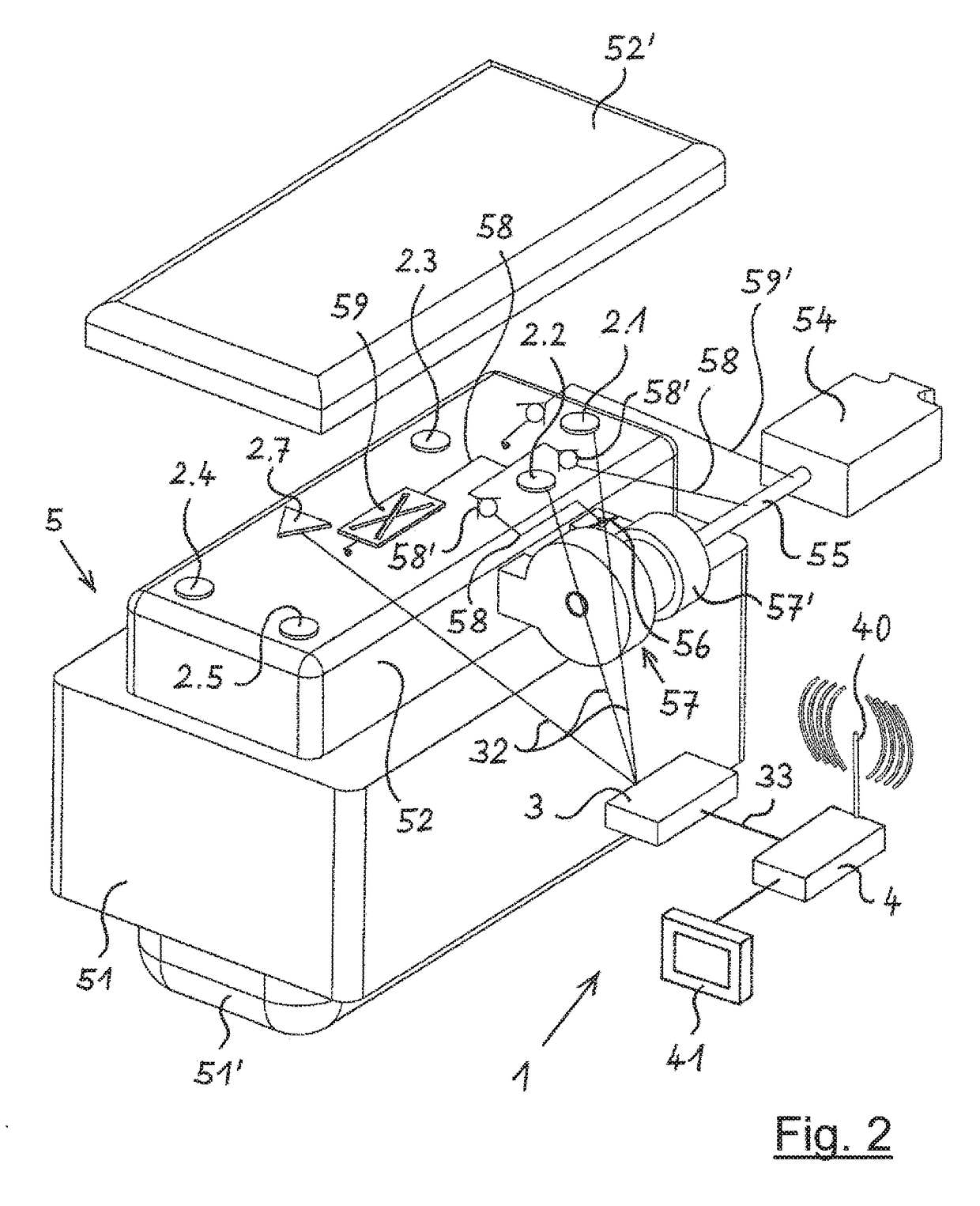
[0041]In engine compartment 61, a plurality of, here a total of six, sensors 2.1 through 2.6 are situated at various locations, which sensors are sensitive to crankcase ventilation gas or to at least one crankcase ventilation gas com...


PUM


Abstract

A method and a device for monitoring the functioning of a crankcase ventilation system of an internal combustion engine, crankcase ventilation gas being supplied to an intake line of the internal combustion engine via at least one crankcase ventilation line from the crankcase via an oil separator and a crankcase pressure regulating valve. An immediate surrounding environment of the internal combustion engine is monitored by at least one sensor that is sensitive to crankcase ventilation gas or to at least one crankcase ventilation gas component for the occurrence of crankcase ventilation gas, and that, if a presence of crankcase ventilation gas is determined, an informative or warning message is produced.

Description

BACKGROUND OF THE INVENTION[0001]The present invention relates to a method for monitoring the functioning of a crankcase ventilation system of an internal combustion engine, crankcase ventilation gas being supplied to an intake line of the internal combustion engine via at least one crankcase ventilation line from the crankcase via an oil separator and a crankcase pressure regulating valve.[0002]In addition, the present invention relates to a device for monitoring the functioning of a crankcase ventilation system of an internal combustion engine, at least one crankcase ventilation line being routed from the crankcase to an intake line of the internal combustion engine, and an oil separator and a crankcase pressure regulating valve being situated in the course of the crankcase ventilation line.[0003]In addition to the combustion exhaust gases, led away by an exhaust system of an internal combustion engine through exhaust gas purification devices such as oxidation catalytic converters...

Claims


Application Information

Patent Timeline
Patent Type & Authority Applications(United States)
IPC IPC(8): G07C5/08F01M13/04G07C5/00
CPCG07C5/0808G07C5/0825G07C5/008F01M13/04F01M2250/00
Inventor AHLBORN, STEPHANPOLLOCK, DAVID MARK
Owner HENGST WALTER
Why Eureka
Try Eureka