
Multi-rotor turbine arranged for coordinated rotational speeds

a multi-rotor, rotating speed technology, applied in the direction of motors, programme control, engine fuction, etc., can solve problems such as challenges in implementation

Active Publication Date: 2018-12-06
VESTAS WIND SYST AS
View PDF11 Cites 5 Cited by
  • Summary
  • Abstract
  • Description
  • Claims
  • Application Information

AI Technical Summary

Benefits of technology

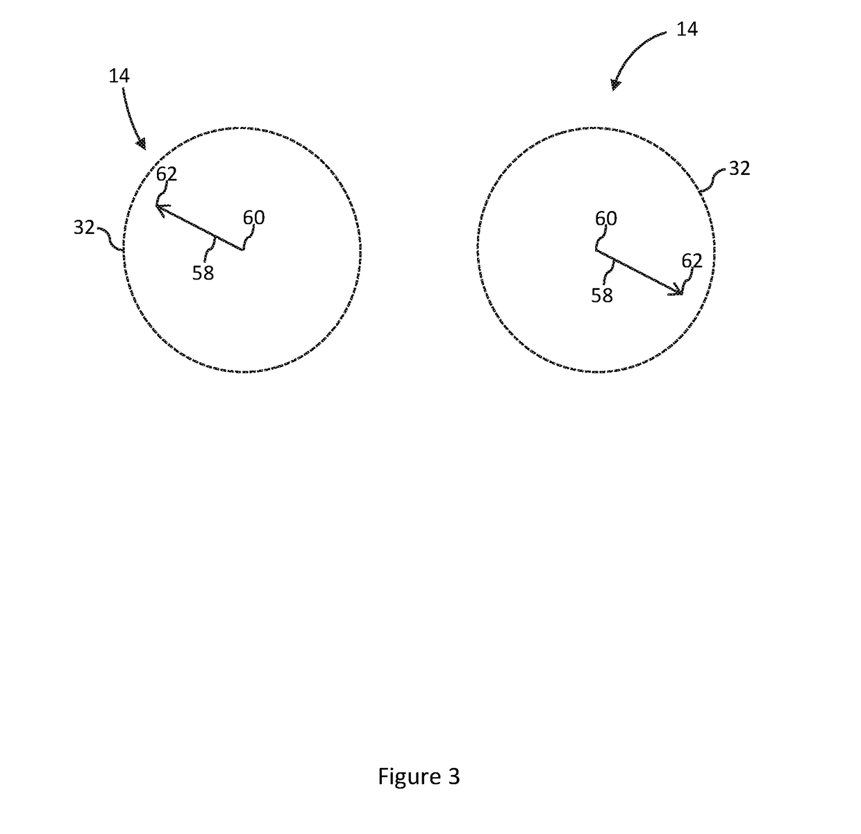
The invention is about a wind turbine system that controls the forces caused by the rotation of the turbine blades to prevent shaking of the support structure. This allows the turbine to operate at certain frequencies without being affected by the shaking, which can reduce its efficiency. The aim is also to prevent the rotor blades from creating a cyclic force that can cause damage to the system.

Problems solved by technology

However, although such a co-planer multi-rotor wind turbine has significant advantages, it presents challenges to implement the concept in practice, particularly in how to control the multiple rotors to achieve optimum power production.

Method used


Image

  • Multi-rotor turbine arranged for coordinated rotational speeds
  • Multi-rotor turbine arranged for coordinated rotational speeds
  • Multi-rotor turbine arranged for coordinated rotational speeds

Examples


Embodiment Construction

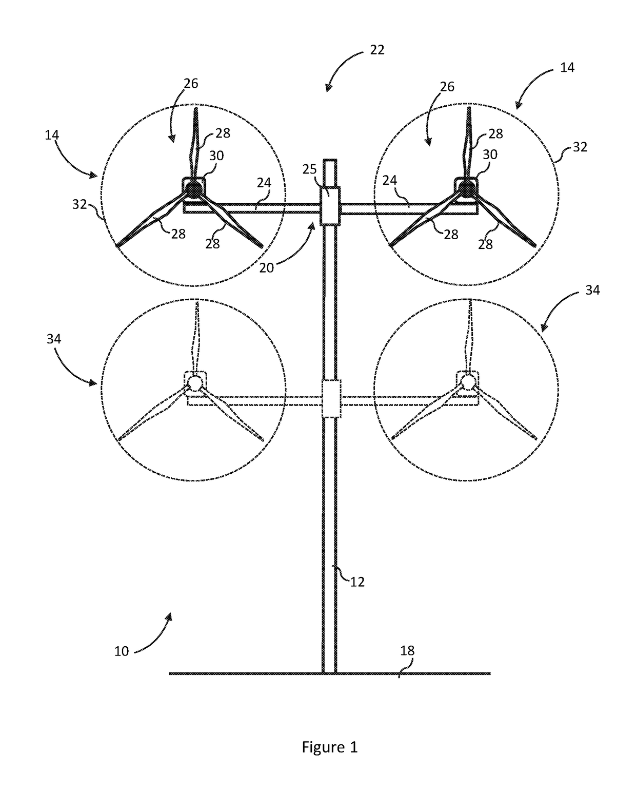
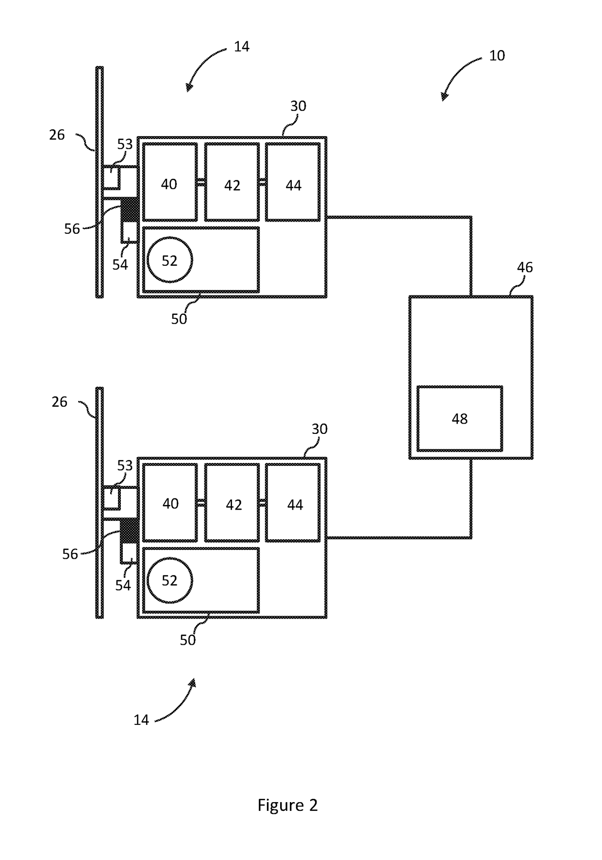
[0024]With reference to FIG. 1, a multi-rotor wind turbine installation 10 is shown including a tower 12 on which is mounted a plurality of wind turbines, or wind turbine modules 14. Note that the term ‘wind turbine’ is used here in the industry-accepted sense to refer mainly to the generating components of the wind turbine installation 10 and as being separate to the tower 12.

[0025]The entire wind turbine installation 10 is supported on a foundation, as is usual. As examples, the foundation may be a large mass buried in the ground 18, as shown here, or in the form of monopole or ‘jacket’ like structure.

[0026]The wind turbine modules 14 are mounted to the tower 12 by a support arm arrangement 20. Together, the tower 12 and the support arm arrangement 20 can be considered to be a support structure 22 of the wind turbine installation 10.

[0027]The support arm arrangement 20 comprises mutually opposed first and second support arms 24 extending generally horizontally from the tower 12, e...


PUM


Abstract

A wind turbine system is described comprising a plurality of wind turbine modules, each including a rotor, mounted to a support structure including a tower. In use, each rotor has an associated rotating unbalance that defines an unbalance vector. The wind turbine system includes control means configured to coordinate the rotational speeds of the plurality of rotors to attenuate oscillations of the support structure caused by the rotating unbalance of the rotors. Also described is a method of controlling such a wind turbine system. The method comprises coordinating the rotational speeds of the plurality of rotors to attenuate oscillations of the support structure caused by the rotating unbalance of the rotors.

Description

TECHNICAL FIELD[0001]The invention relates to a control system for a wind turbine system having multiple rotors and more particularly, but not exclusively, to an array-type, or multi-rotor, wind turbine system in which the separate rotors of the system may be aligned generally in a common plane.BACKGROUND TO THE INVENTION[0002]There exist a number of alternative wind turbine installation designs. One example is the multi-rotor array type wind turbine.[0003]For example, EP1483501 B1 discloses a multi-rotor array-type wind turbine installation in which several co-planar rotors are mounted to a common support structure. Such a configuration achieves economies of scale that can be obtained with a very large single rotor turbine, but avoids the associated drawbacks such as high blade mass, scaled up power electronic components and so on. However, although such a co-planer multi-rotor wind turbine has significant advantages, it presents challenges to implement the concept in practice, par...

Claims


Application Information

Patent Timeline
Patent Type & Authority Applications(United States)
IPC IPC(8): F03D7/02F03D1/02F03D7/04G05B19/042
CPCF03D7/0276F03D1/02F03D7/042G05B19/042F05B2240/912F05B2260/966F05B2270/1013F05B2270/334F05B2220/70646G05B2219/2619F03D7/0296Y02E10/72Y02E10/728
Inventor GRUNNET, JACOB DELEURANMIRANDA, ERIK CARL LEHNSKOVKRABBE, MICHAEL RIIS
Owner VESTAS WIND SYST AS
Learn More