
Inhalation system

a technology of inhalation system and inhalation chamber, which is applied in the direction of inhalators, medical devices, other medical devices, etc., can solve the problems of low effect in relation to the inhalation quantity of aerosol, frequent failure to reach, and high concentration of aerosol entering the patient's mouth, etc., and achieves high level of shape stability and rapid exchange

Inactive Publication Date: 2018-12-06
R CEGLA
View PDF2 Cites 1 Cited by
  • Summary
  • Abstract
  • Description
  • Claims
  • Application Information

AI Technical Summary

Benefits of technology

The present invention provides an inhalation arrangement with a valve that can be easily and hygienically used. The valve allows for a linear and rotating motion of the aerosol during inhalation, which ensures even distribution of the aerosol to the patient's treatment area. The valve is fixed in a precise position on the container, which allows for easy sterilization or cleaning. The valve is made of elastically deformable material, which ensures that the valve can be in a stable position and will not kink or snap through easily.

Problems solved by technology

Although handling of the inhalation arrangement is simple and can be accomplished hygienically because the individual components forming the inhalation arrangement can be sterilised, it has proven to be a disadvantage in this state of the art that there is an almost linear, cylindrical air flow during the inhalation procedure because the cross-slits worked into the diaphragm are at right angles to one another, with the effect that these scarcely exert any influence on the flow of the aerosol flowing from the first to the second chamber.
As a result, highly concentrated aerosol enters the patient's mouth, and has a low effect in relation to the inhaled quantity of aerosol because there is no optimum distribution of the aerosol in the respiratory passages and it frequently fails to reach the bronchi or lungs in adequate quantity because the aerosol has already been deposited on the mucous membranes of the mouth or throat.

Method used


Image

  • Inhalation system
  • Inhalation system

Examples


Embodiment Construction

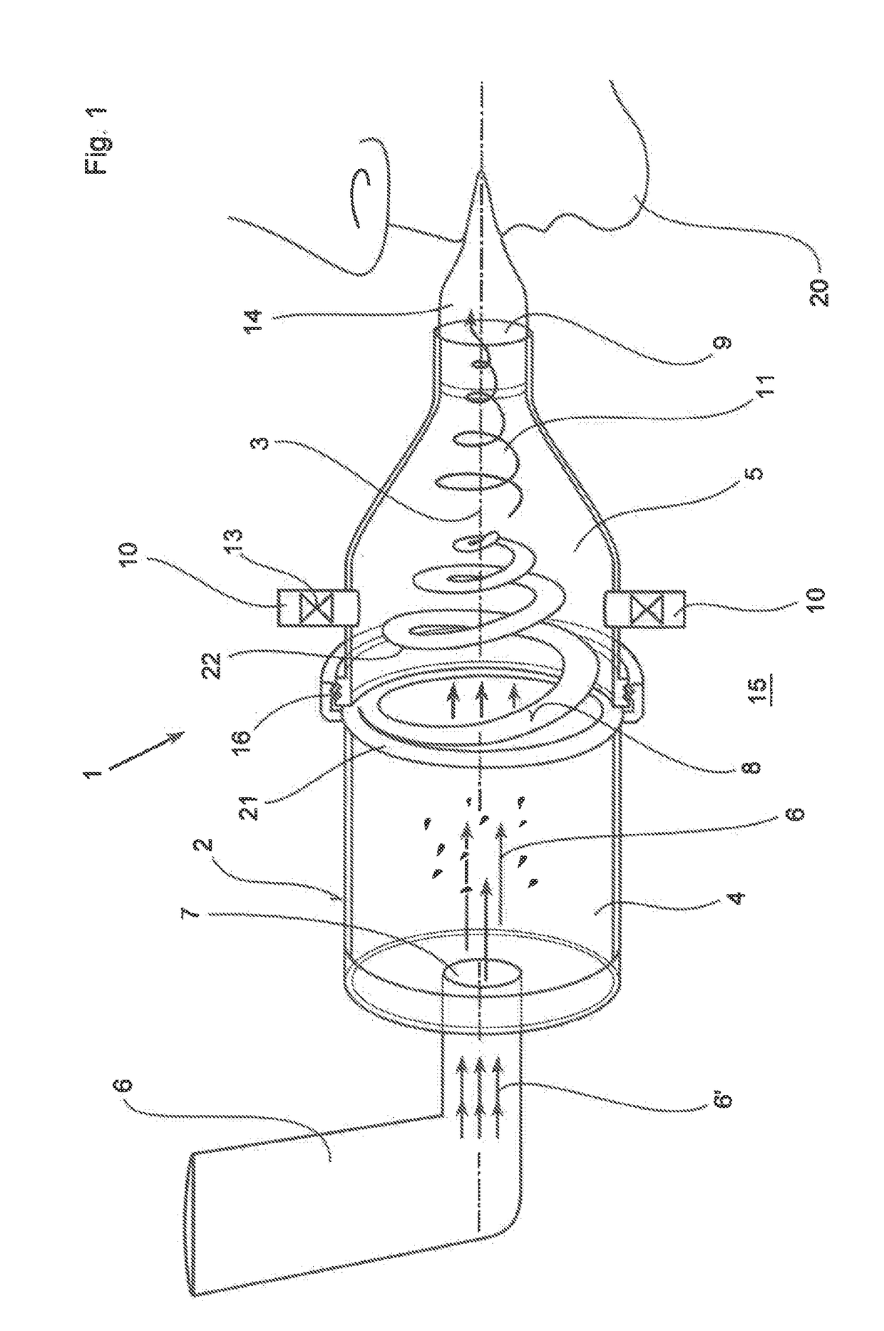
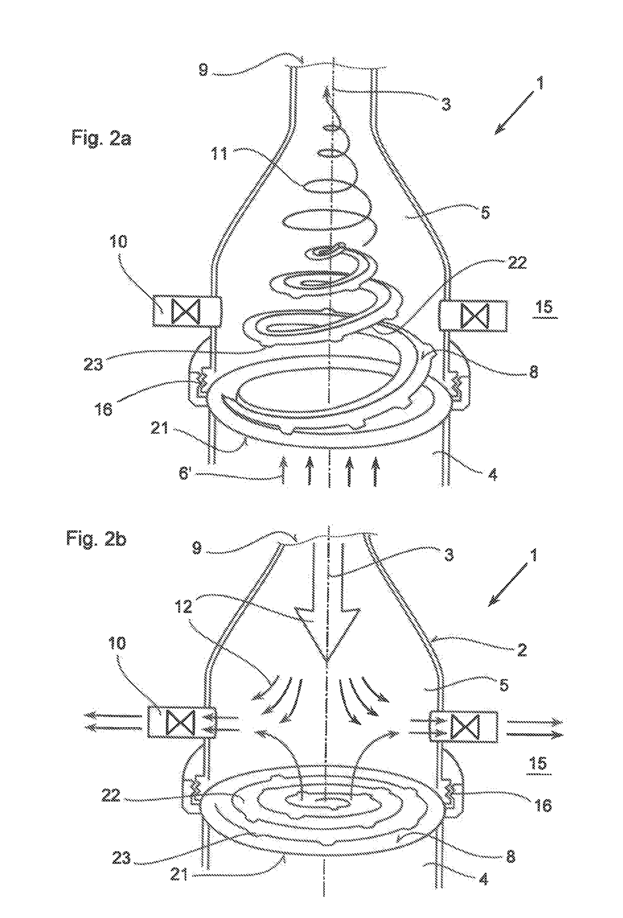
[0017]FIGS. 1 and 2a show an inhalation system 1 which serves the purpose of transporting an aerosol 6′ delivered by a dosing device 6 to a human being 20 for the treatment of respiratory passage illnesses. In particular, it is to be ensured that the dosing aerosol 6′ reaches the bronchial area of the patient 20 as evenly and optimally dosed as possible, and can be deposited evenly on the parts of the human being 20 which are to be treated.

[0018]The inhalation system 1 consists of a container 2 with a longitudinal axis with the reference number 3. The container 2 has two parts which are connected together but can be released. The transitional area between the two parts of the container 2 is defined as the parting plane into which a valve 8 explained in more detail below is inserted and locked in an orientated position. As a result, two chambers 4 and 5 are created inside the container 2 which are separated from one another by means of the valve 8, although they can communicate with ...


PUM


Abstract

In an inhalation system (1) for inhalation of a dosing aerosol (6′), comprising:a dosing device (6) which delivers the aerosol (6′)a container (2) in which one or more chambers (4, 5) separated from one another and connected together during inhalation by means of one or more valves (8) are provided,with an inlet opening (7) emerging into the first chamber (4), into which opening the dosing device (6) is inserted,with the second chamber (5) having a first passage opening (9) which interacts with the respiratory openings of a human being (20),with the second chamber (5) having a second passage opening (10) that is connected to the surrounding air (15) and through which a positive pressure in the second chamber (5) can escape into the surrounding air (15) during exhalation, a simple and hygienic application of the inhalation arrangement (1) should be guaranteed and the aerosol flow should have a linear and rotating motion induced in it during the inhalation procedure.This is achieved in thatthe valve (8) is formed from an elastically deformable material, preferably silicone, that the valve (8) has a ring-shaped circumferential collar (21) that is fixed to the container (2),at least one slot-shaped notch (22) is worked into the valve (8) which is configured as a spiral running from inside to outside,that during inhalation, the valve (8) acts as a barrier to the flow of the aerosol (6′) flowing through it, as a result of which a linear motion and a spiral-shaped flow direction (11) along and about the longitudinal axis (3) of the container (2) is imposed on the aerosol (6′), channelling it into a three-dimensional spiral

Description

REFERENCE TO PENDING PRIOR PATENT APPLICATION[0001]This patent application claims benefit of European Patent Application No. 17 174 196.0, filed Jun. 2, 2017, which patent application is hereby incorporated herein by reference.FIELD OF THE INVENTION[0002]The present invention relates to an inhalation system for inhaling a dosed aerosol in accordance with the pre-characterising clauses of patent claim 1.BACKGROUND OF THE INVENTION[0003]An inhalation arrangement of this kind has been disclosed, for example, in EP 2 678 060 B1. Inhalation arrangements of this kind consist of a container with two chambers connected together by means of a valve. In the aforementioned state of the art, the valve is configured as a diaphragm into which two slits running at right angles to one another are worked, the slits closing during the exhalation procedure; on the other hand, during inhalation the cross-slits formed in this way are opened with the result that the aerosol input into the first chamber c...

Claims


Application Information

Patent Timeline
IPC IPC(8): A61M15/00
CPCA61M15/002A61M15/009A61M2206/12A61M2206/20A61M15/0086A61M16/208A61M2206/16A61M15/0016A61M15/0018A61M16/209
Inventor CEGLA, ULRICH HARTMANN
Owner R CEGLA
Learn More