Snow blowing apparatus

a technology of snow blowing apparatus and snow blowing ice, which is applied in the direction of process and machine control, vehicle position/course/altitude control, instruments, etc., can solve the problems of constant winter snowfall on roadways and sidewalks, danger of falling off and falling on ice, injury, etc., and achieves the effect of fast, painless and tiring labor

Inactive Publication Date: 2018-10-25
LOGHRY SR JOHN CLIFFORD
View PDF0 Cites 2 Cited by
  • Summary
  • Abstract
  • Description
  • Claims
  • Application Information

AI Technical Summary

Benefits of technology

This patent describes an improved snow blowing apparatus that has a housing, rear wheels, an intake portion, an impeller, and a pivot motor. These components work together to make the snow blowing apparatus move and blow snow. The apparatus also has a microcontroller that allows users to control the motors and the movements of the snow blowing apparatus through a computer. The technical effects of this invention include improved efficiency, control, and user experience when snow blowing.

Problems solved by technology

One of the disadvantages is the constant wintertime snowfall on roadways and sidewalks.
Driveways tend to get covered in deep snow, that in a short amount of time, can block vehicles from entering to park or from leaving once the vehicle is parked.
The danger of slipping and falling on ice and becoming injured is always present.
The labor is almost always tiring and painful.
It is a special problem for those with health issues that interfere, which complicates the task.
While they are labor reducing, they still consume time and the labor of pushing, pulling, and turning.

Method used


Image

  • Snow blowing apparatus
  • Snow blowing apparatus
  • Snow blowing apparatus

Examples


Embodiment Construction

[0022]As discussed above, embodiments of the present invention relate to a snow blower and more particularly to an improved snow blower apparatus as used to improve the automated and remote control use.

[0023]Generally speaking, an improved snow blower apparatus is a snow blower that is able to be remotely controlled by a user located at a remote location. At least one video camera located on the snow blower allows the user to view the environment around the snow blower for safety purposes and to control the direction of travel and speed of the apparatus.

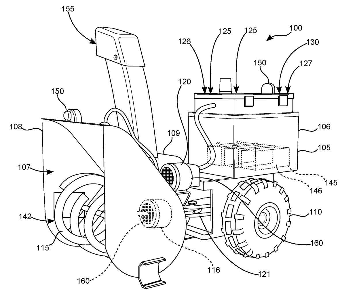
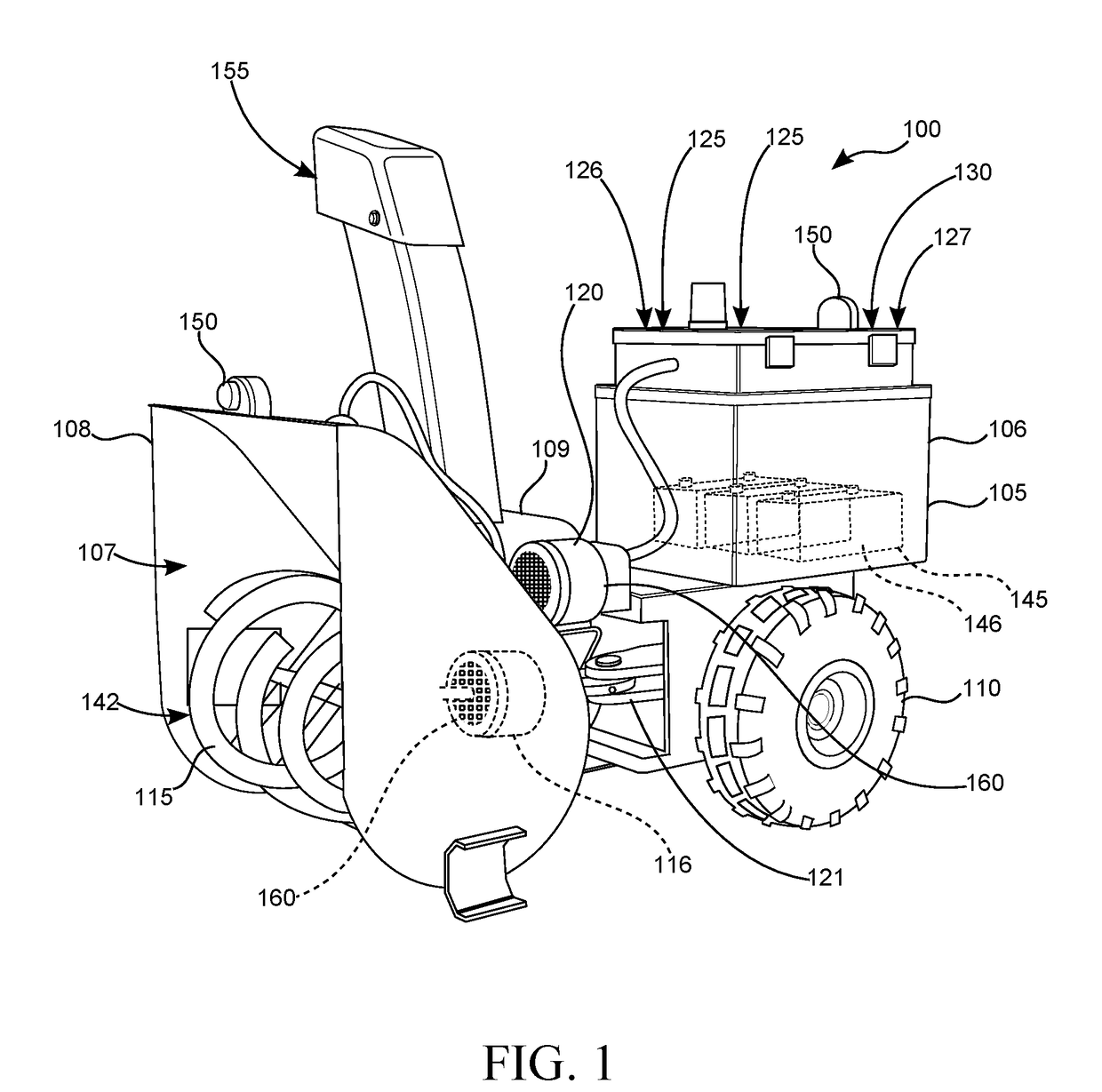
[0024]Referring to the drawings by numerals of reference there is shown in FIG. 1, a perspective view illustrating improved snow blowing apparatus 100 according to an embodiment of the present invention.

[0025]Improved snow blowing apparatus 100 may comprise housing 105, a pair of rear wheels 110 rotatably connected to rear portion 106 of housing 105, intake portion 107 connected to front portion 108 of housing 105 opposite rear porti...


PUM


Abstract

An improved snow blower apparatus is a snow blower that is able to be remotely controlled by a user located at a remote location. At least one video camera located on the snow blower allows the user to view the environment around the snow blower for safety purposes and to control the direction of travel and speed of the apparatus.

Description

CROSS-REFERENCE TO RELATED APPLICATION[0001]The present application is related to and claims priority from prior provisional application Ser. No. 62 / 488126, filed Apr. 21, 2017 which application is incorporated herein by reference.COPYRIGHT NOTICE[0002]A portion of the disclosure of this patent document contains material which is subject to copyright protection. The copyright owner has no objection to the facsimile reproduction by anyone of the patent document or the patent disclosure, as it appears in the Patent and Trademark Office patent file or records, but otherwise reserves all copyright rights whatsoever. 37 CFR 1.71(d).BACKGROUND OF THE INVENTION[0003]The following includes information that may be useful in understanding the present invention(s). It is not an admission that any of the information provided herein is prior art, or material, to the presently described or claimed inventions, or that any publication or document that is specifically or implicitly referenced is pri...

Claims


Application Information

Patent Timeline
IPC IPC(8): G05D1/00E01H5/09
CPCG05D1/0016E01H5/098G05D1/0038G05D1/0022G05D1/0055
Inventor LOGHRY, SR., JOHN CLIFFORD
Owner LOGHRY SR JOHN CLIFFORD
Why Eureka
Try Eureka