Construction machine
- Summary
- Abstract
- Description
- Claims
- Application Information
AI Technical Summary
Benefits of technology
Problems solved by technology
Method used
Image

Examples
first embodiment
[0021]With reference to FIGS. 1 to 9, a construction machine 1 of a first embodiment will be described.
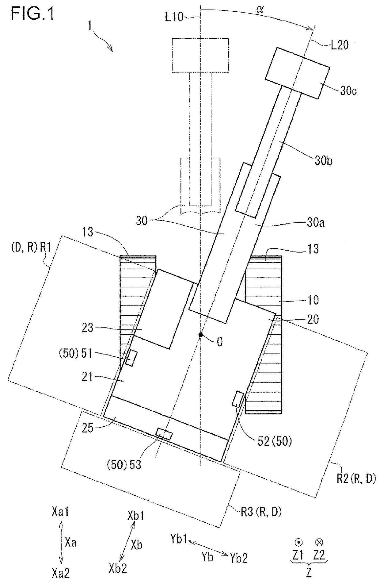
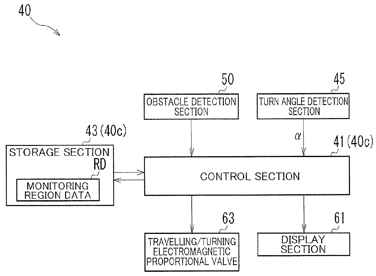
[0022]The construction machine 1, which is a machine that conducts work such as construction work and is a machine that conducts work such as digging work, is, for example, a shovel, or a hydraulic excavator. The construction machine 1 includes a lower travelling body 10, an upper slewing body 20, an upper attachment 30, and a control system 40 (see FIG. 2).
[0023]The lower travelling body 10 is a part of the construction machine 1 which travels on the ground. As shown in FIG. 5, the lower travelling body 10 includes a lower main body 11 (a main body portion), and a pair of right and left crawlers 13. To the lower main body 11, a lower attachment (structure) such as a dozer may be attached in some cases. The lower attachment is included in the lower travelling body 10. The right and left crawlers 13 are attached to a left side portion and a right side portion of the lower main body ...
second embodiment
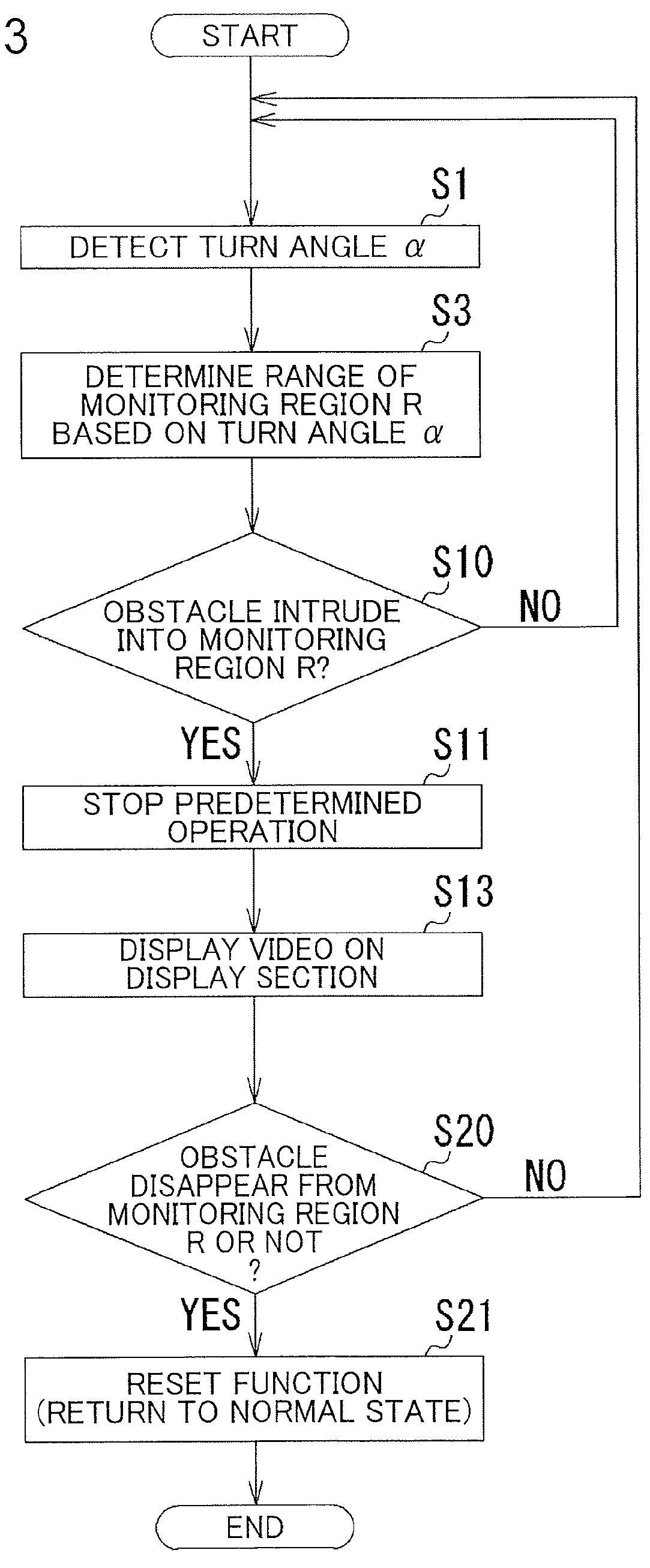
[0079]With respect to a construction machine 201 of a second embodiment, differences from the above embodiment will be described with reference to FIGS. 10 to 14. Of the construction machine 201 of the second embodiment, common parts to those of the first embodiment are given the same reference codes as those of the first embodiment to omit description thereof (omission of description of common parts is also the case with description of a third embodiment). While in the first embodiment, the monitoring region R is changed by changing the angle of view β of the obstacle detection section 50 shown in FIG. 5, in the present embodiment, with the angle of view β of the obstacle detection section 50 shown in FIG. 11 fixed, the monitoring region R is changed by changing an excluded region E.
[0080]The control section 41 (see FIG. 2) determines, as the monitoring region R, a region obtained by excluding the excluded region E (when expressed in a different way, subtracting) from the detection...
third embodiment
[0086]With respect to a construction machine 301 of a third embodiment, differences from the first embodiment will be described with reference to FIG. 15. In the construction machine 1 (i.e. a conventional machine) of the first embodiment shown in FIG. 1, when the upper slewing body 20 turns, when seen from the up-down direction Z, the end portion on the upper slewing body rear side Xb2 of the upper slewing body 20 protrudes from either the right or left crawler 13. On the other hand, in the construction machine 301 (i.e. a rear small slewing machine) of the present embodiment shown in FIG. 15, when the upper slewing body 20 turns, when seen from the up-down direction Z, the end portion on the upper slewing body rear side Xb2 of the upper slewing body 20 does not protrude (or hardly protrude) from either the right or left crawler 13. Therefore, provision of the left side sensor 51 and the right side sensor 52 shown in FIG. 1 may not necessarily be required. In the construction machi...
PUM
 Abstract
Description
Claims
Application Information
 - R&D
- Intellectual Property
- Life Sciences
- Materials
- Tech Scout
- Unparalleled Data Quality
- Higher Quality Content
- 60% Fewer Hallucinations
Browse by: Latest US Patents, China's latest patents, Technical Efficacy Thesaurus, Application Domain, Technology Topic, Popular Technical Reports.
© 2025 PatSnap. All rights reserved.Legal|Privacy policy|Modern Slavery Act Transparency Statement|Sitemap|About US| Contact US: help@patsnap.com