
Cardiac implant delivery system

Active Publication Date: 2018-05-17
EVALVE
View PDF10 Cites 21 Cited by
  • Summary
  • Abstract
  • Description
  • Claims
  • Application Information

AI Technical Summary

Benefits of technology

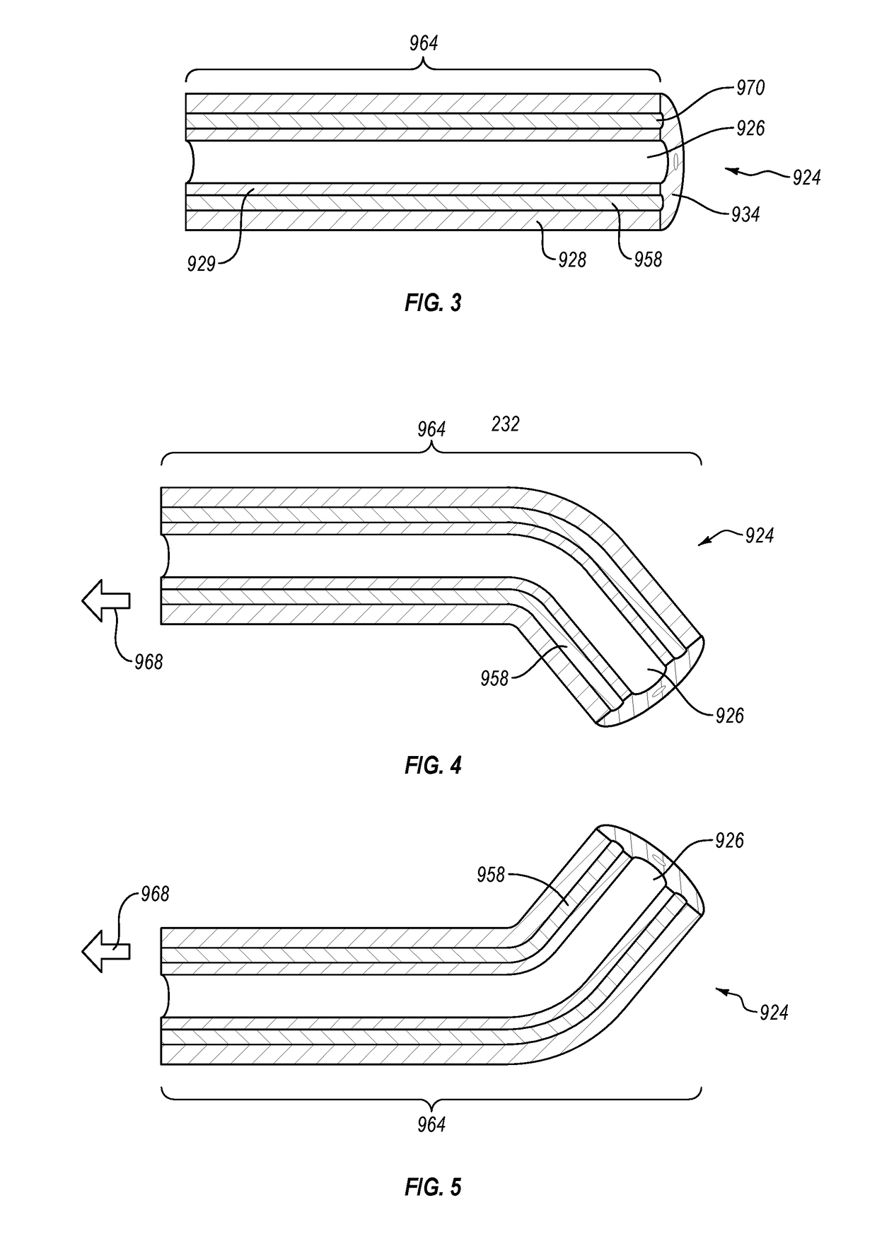
The patent text describes a delivery system for replacement heart valves that includes a catheter and a sheath. The catheter has a rotatable control and a gear assembly that reduces the tensioning of the control wire. The steerable catheter has cuts to increase flexibility and bending preferences. The delivery system can deploy a replacement heart valve in a targeted area within the body by using fluid to cause the sheath to move and release the replacement heart valve.

Problems solved by technology

One problem often requiring a valve replacement is mitral valve regurgitation.
When the mitral valve is in a regurgitant condition, the mitral valve does not properly close, allowing oxygenated blood to flow backwards in the heart.
As a result, blood is not moved as efficiently through the heart and the rest of the body, often leaving people with symptoms including shortness of breath, irregular heartbeats, and chest pain.
However, precise delivery of replacement heart valves remains a challenge due to the structure at or near the target location or due to the particular demands of the implant to be delivered.
Further, while some catheter guiding systems adapted for use in other interventional cardiac procedures are available, there exist additional challenges that limit effective use of such catheter guiding systems for delivery and deployment of replacement valve implants.
In addition, replacement heart valve implants are often inherently bulkier than other interventional implant devices, increasing difficulties in steering and positioning of the replacement valve.
Further, heart valve target areas can often be difficult to reach, requiring a relatively tortuous path and / or relatively high turn curvatures to obtain proper alignment and orientation of the delivered implant.

Method used


Image

  • Cardiac implant delivery system
  • Cardiac implant delivery system
  • Cardiac implant delivery system

Examples


Embodiment Construction

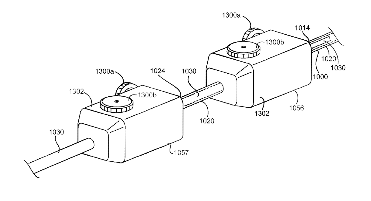
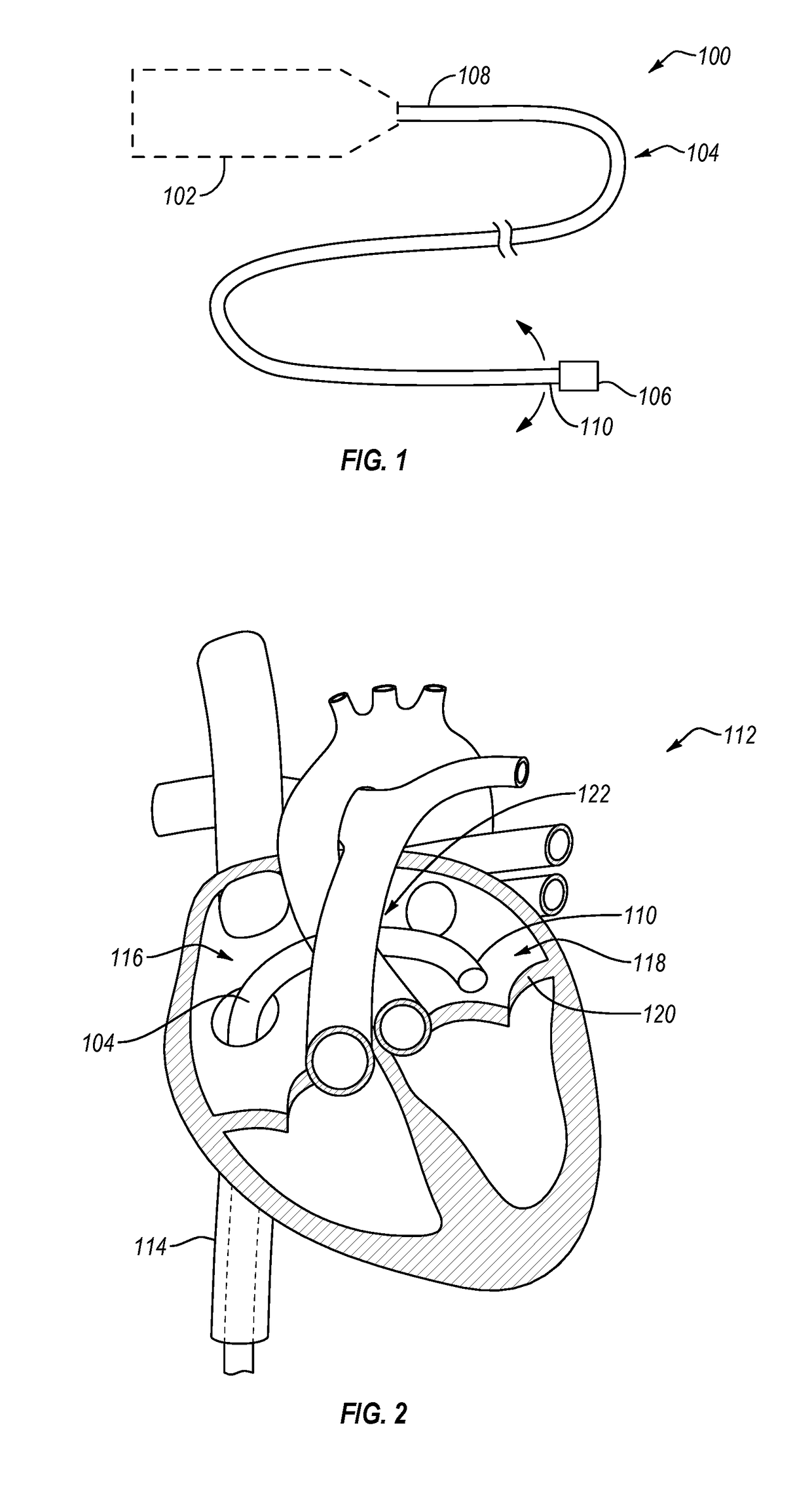
[0032]One or more embodiments described herein relate to replacement heart valve delivery systems. Certain embodiments described herein are adapted to enable effective delivery and deployment of a replacement heart valve at a targeted area of a patient. As described herein, at least some of the delivery systems include one or more features or components which enhance the effectiveness of the delivery systems when used in applications for delivering and deploying a replacement heart valve. In some embodiments, one or more components or features of a replacement valve delivery system distinguish the replacement valve delivery system from other delivery systems typically used for delivery of other interventional cardiac devices, and thereby offer advantages and benefits not obtainable by the other delivery systems, particularly in implementations of delivering and deploying a replacement heart valve.

[0033]Throughout this disclosure, many examples are described in the context of deliver...


PUM


Abstract

The present disclosure relates to delivery systems for delivering and deploying interventional devices to a targeted area within a body, such as delivering a replacement heart valve to a targeted heart valve. A delivery device includes a steerable catheter and a replacement valve delivery system positioned within the steerable catheter and configured to be translatable within the steerable catheter. The steerable catheter includes one or more control wires running from a distal end of the catheter to a handle at the proximal end of the catheter. Each control wire is coupled to a control of the handle such that manipulation of the control provides deflection and control of the steerable catheter.

Description

CROSS-REFERENCE TO RELATED APPLICATIONS[0001]N / ABACKGROUND[0002]Heart valve diseases are often treated by replacing the malfunctioning heart valve with a replacement valve implant. Heart valves that are replaced with replacement valve implants include the mitral valve, the aortic valve, the tricuspid valve, and the pulmonary valve, with the mitral valve and the aortic valve being the most commonly replaced valves. Typically, heart valves are replaced to address undesirable stenosis (i.e., narrowing) of a valve, or to correct regurgitation caused by an improperly functioning valve. One problem often requiring a valve replacement is mitral valve regurgitation. When the mitral valve is in a regurgitant condition, the mitral valve does not properly close, allowing oxygenated blood to flow backwards in the heart. As a result, blood is not moved as efficiently through the heart and the rest of the body, often leaving people with symptoms including shortness of breath, irregular heartbeats...

Claims


Application Information

Patent Timeline
IPC IPC(8): A61F2/24A61B90/00A61M25/01
CPCA61F2/2436A61B90/06A61M25/0136A61B2090/066A61M25/0158A61F2/2439A61F2002/485A61M25/0147A61F2/97A61F2002/9665A61F2250/0071A61F2/9517A61F2/484
Inventor PRABHU, SANTOSH V.
Owner EVALVE
Learn More