Gate driving circuit and switching power supply device
a driving circuit and switching power supply technology, applied in electronic switching, power conversion systems, pulse techniques, etc., can solve the problems of complex configuration of the entire circuit and the number of components, and achieve the effect of suppressing surge voltage and switching loss, and simple configuration
- Summary
- Abstract
- Description
- Claims
- Application Information
AI Technical Summary
Benefits of technology
Problems solved by technology
Method used
Image
Examples
first embodiment
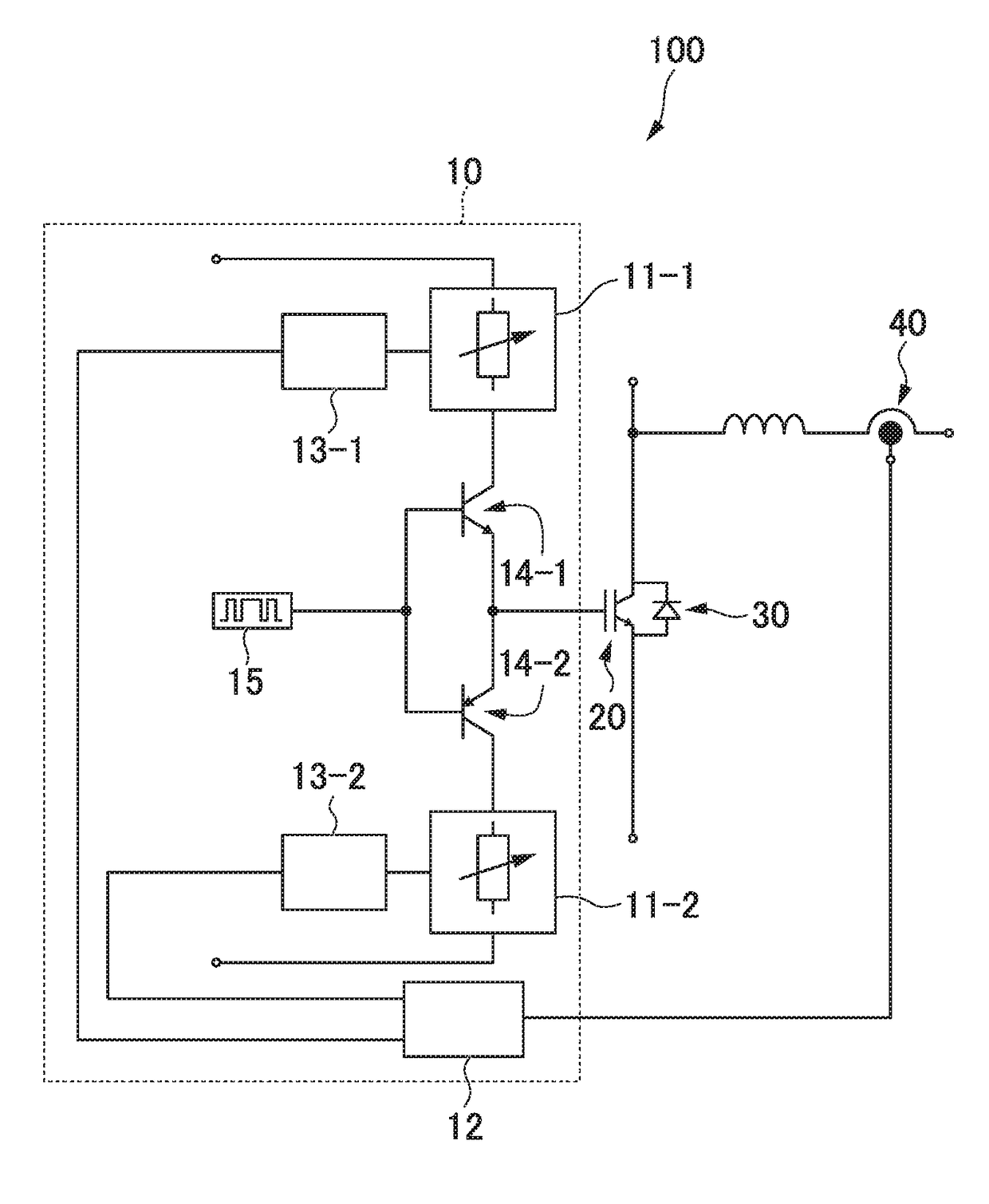
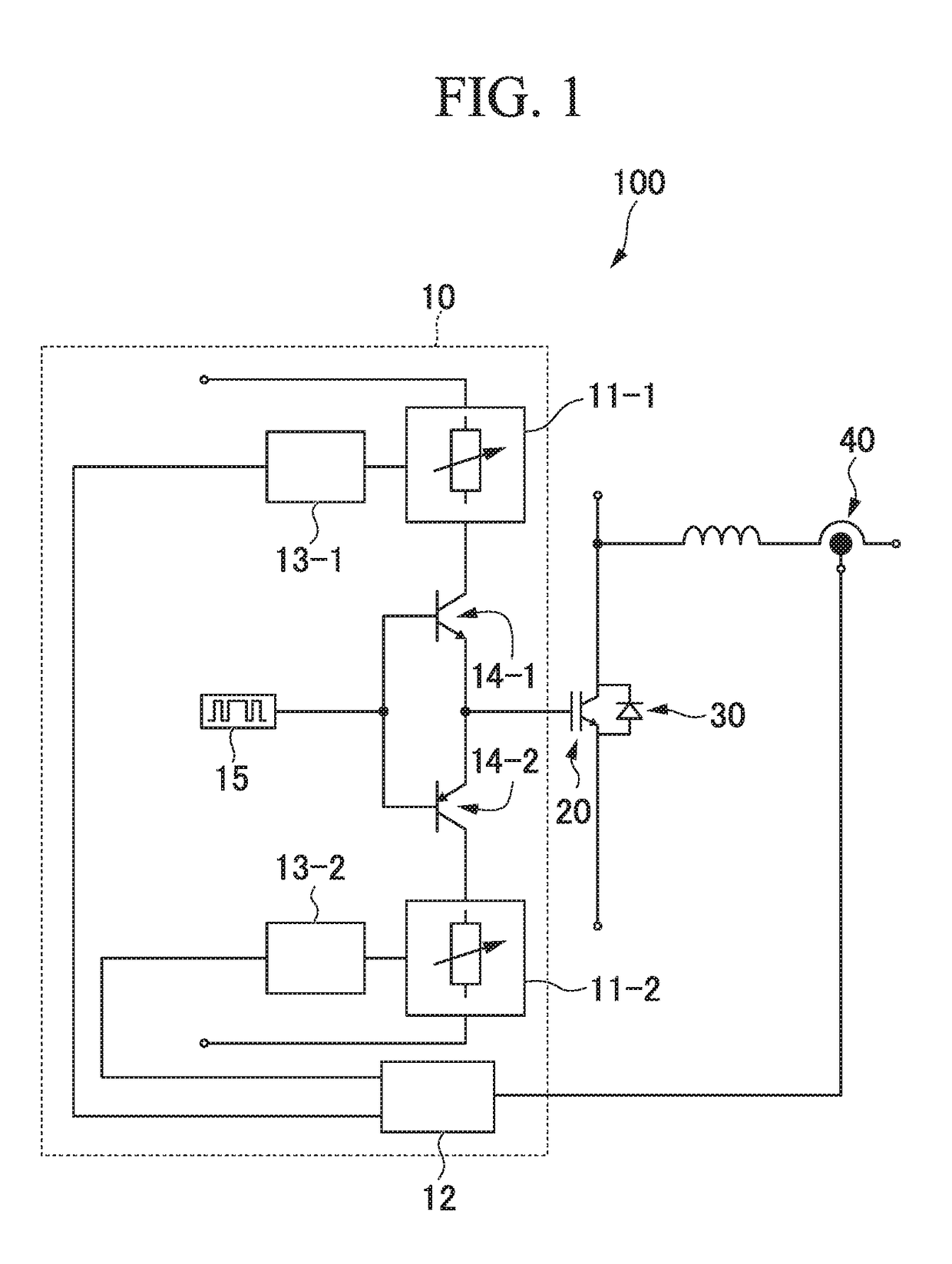
[0049]FIG. 1 is a circuit diagram illustrating a switching power supply device 100 to which the gate driving circuit 10 of the first embodiment is applied. The gate driving circuit 10 illustrated in FIG. 1 includes gate resistors connected to a main switching element 20, and the gate resistors include voltage controlled resistors 11-1 and 11-2 of which the resistance value can be continuously changed. Further, the gate driving circuit 10 includes switching elements 14-1 and 14-2, and a signal source 15. Further, a freewheeling diode 30 is connected in reverse parallel to the main switching element 20.
[0050]In the example illustrated in FIG. 1, an end on one side (the upper side in FIG. 1) of the voltage controlled resistor 11-1 is connected to a high potential, and an end on the other side (the lower side in FIG. 1) of the voltage controlled resistor 11-1 is connected to the main switching element 20 via the switching element 14-1. Further, the main switching element 20 is connected...
second embodiment
[0066]FIG. 6 is a circuit diagram illustrating a switching power supply device 100 to which a gate driving circuit 10 of a second embodiment is applied. The gate driving circuit 10 illustrated in FIG. 1 includes two voltage controlled resistors 11-1 and 11-2 of which the resistance value can be continuously changed, whereas the gate driving circuit 10 illustrated in FIG. 6 includes one voltage controlled resistor 11 of which the resistance value can be continuously changed. The voltage controlled resistor 11 functions as a gate resistor connected to the main switching element 20, similar to the voltage controlled resistors 11-1 and 11-2.
[0067]In the example illustrated in FIG. 6, an end on one side (left side in FIG. 6) of the voltage controlled resistor 11 is connected to switching elements 14-1 and 14-2, and an end on the other side (right side inFIG. 6) of the voltage controlled resistor 11 is connected to the main switching element 20. The switching elements 14-1 and 14-2 are co...
PUM
 Abstract
Description
Claims
Application Information
 - R&D
- Intellectual Property
- Life Sciences
- Materials
- Tech Scout
- Unparalleled Data Quality
- Higher Quality Content
- 60% Fewer Hallucinations
Browse by: Latest US Patents, China's latest patents, Technical Efficacy Thesaurus, Application Domain, Technology Topic, Popular Technical Reports.
© 2025 PatSnap. All rights reserved.Legal|Privacy policy|Modern Slavery Act Transparency Statement|Sitemap|About US| Contact US: help@patsnap.com


