Method of minimizing stitching artifacts for overlapping printhead segments

Active Publication Date: 2018-05-10
MEMJET TECH LTD
View PDF3 Cites 0 Cited by
  • Summary
  • Abstract
  • Description
  • Claims
  • Application Information

AI Technical Summary

Benefits of technology

This patent text describes a method for determining a continuous seam in a printed image. The method uses a cost function that includes parameters such as minimizing the density of printed ink and maximizing luminance along the seam. This method helps to reduce stitching artifacts in printed images and improves the overall image quality.

Problems solved by technology

A problem with overlapping printhead segments is that pairs of neighbouring printhead segments must be stitched together in their overlap regions.
Whatever stitching method is used, print artifacts generally result from the stitching, either in the form of a light or dark streak down the page.
However, a problem with all stitching techniques is that the relative positioning of the overlapping printhead segments is never precisely known and, moreover, cannot be controlled to the necessary degree of accuracy during printhead manufacture or printhead replacement.
A further problem is that two dots printed on top of each other typically produce a higher optical density than simply printing the same two dots separately.
Therefore, producing a predictable optical density in the overlap region is virtually impossible, because overlapping dithers from overlapping printheads will produce an unpredictable number of dot-on-dot artifacts depending on the precise registration of the printheads.
Surprisingly, unsophisticated butt joins often produce the best results for many types of image content due to the above-mentioned problems with more sophisticated dithering methods.
Nevertheless, butt joins are far from satisfactory when printhead segments are misaligned and / or somewhat rotated relative to each other.

Method used


Image

  • Method of minimizing stitching artifacts for overlapping printhead segments
  • Method of minimizing stitching artifacts for overlapping printhead segments
  • Method of minimizing stitching artifacts for overlapping printhead segments

Examples


Embodiment Construction

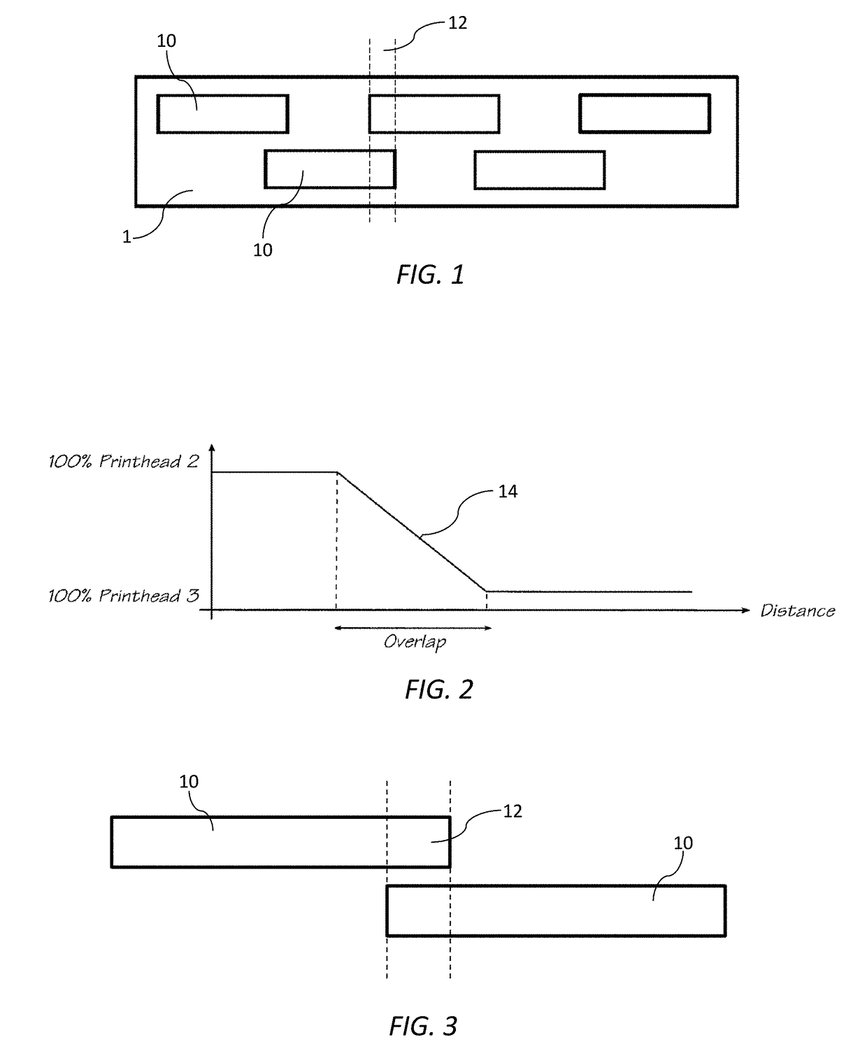
[0092]Referring to FIG. 1, there is shown schematically a print bar 1 comprising a fixed array of five overlapping printhead segments. Each printhead segment takes the form of an elongate inkjet printhead 10 (e.g. A4-sized printhead) having rows of nozzles (not shown) for ejection of ink. In FIG. 1, the five printheads are nominally designated Printhead 1, Printhead 2, Printhead 3 etc from left to right. In the print bar 1 shown in FIG. 1, the printheads 10 are all monochrome printheads, although it will be appreciated that multi-color printheads are, of course, with the ambit of the present disclosure.

[0093]Neighbouring overlapping printheads 10 have an overlap region 12 whereby nozzles from either of the overlapping printheads may be used to print a strip of an image corresponding to the overlap region. In these overlap regions 12, the neighbouring printheads 10 must be stitched together to avoid discontinuities in the printed image.

[0094]One prior art stitching method (known in t...


PUM


Abstract

A method of printing an image using a printing system having first and second overlapping printhead segments. The method includes the steps of: (i) identifying a strip of the image to be printed in an overlap region of the first and second printhead segments; (ii) determining a continuous seam in the strip based on a cost function, the cost function including a parameter selected from the group consisting of: (a) minimizing a density of printed ink along the seam; and (b) maximizing a luminance along the seam; and (iii) printing the image using the first and second printhead segments, the printing including stitching the first and second printhead segments across the seam. The strip contains variable image content and the seam has a varying position within the strip.

Description

CROSS-REFERENCE TO RELATED APPLICATION[0001]This application claims the benefit of priority under 35 U.S.C. § 119(e) of U.S. Provisional Application No. 62 / 412,742, filed Oct. 25, 2016, and entitled METHOD OF MINIMIZING STITCHING ARTIFACTS FOR OVERLAPPING PRINTHEAD SEGMENTS, the disclosure of which is hereby incorporated by reference in it entirety for all purposes.FIELD OF THE INVENTION[0002]The present invention relates generally to printing systems having overlapping printhead segments. It has been developed primarily for minimizing stitching artifacts in overlap regions.BACKGROUND[0003]Pagewide printing dramatically increases print speeds compared to traditional scanning printheads. Many types of pagewide printers use overlapping printhead segments to form a pagewide array configured for printing over a required media width. For example, the Applicant's wideformat pagewide printers described in WO2011 / 011824 use a staggered overlapping array of multi-color A4-sized printheads, w...

Claims


Application Information

Patent Timeline
IPC IPC(8): B41J3/54B41J2/21B41J2/045B41J2/07
CPCB41J2/07B41J3/543B41J2/2132B41J2/04518B41J2/2146B41J19/145G06K15/107H04N1/56H04N1/58G06T3/04H04N1/4078G06K15/1223
Inventor LAU, DANIEL
Owner MEMJET TECH LTD
Why Eureka
Try Eureka