Five-piece optical imaging lens
- Summary
- Abstract
- Description
- Claims
- Application Information
AI Technical Summary
Benefits of technology
Problems solved by technology
Method used
Image
Examples
first embodiment
[0039]The equation for the aspheric surface profiles of the first embodiment is expressed as follows:
z=ch21+[1-(k+1)c2h2]0.5+Ah4+Bh6+Ch8+Dh10+Eh12+Gh14+…
[0040]z represents the distance of a point on the aspheric surface at a height h from the optical axis 190 relative to a plane perpendicular to the optical axis at the vertex of the aspheric surface;
[0041]c is a paraxial curvature equal to 1 / R (R:a paraxial radius of curvature);
[0042]h represents a vertical distance from the point on the curve of the aspheric surface to the optical axis 190;
[0043]k represents the conic constant;
[0044]A, B, C, D, E, G . . . : represent the high-order aspheric coefficients.
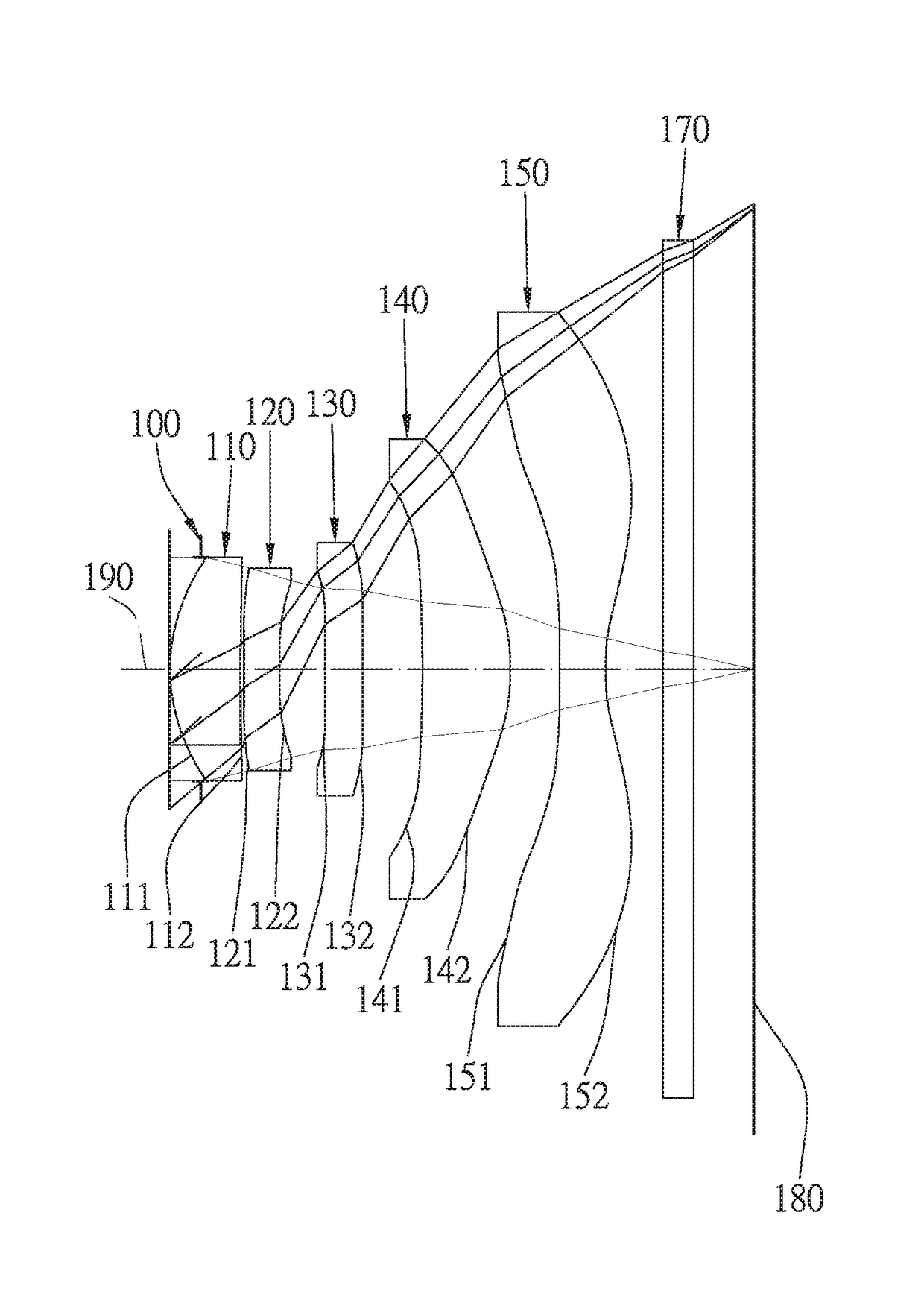
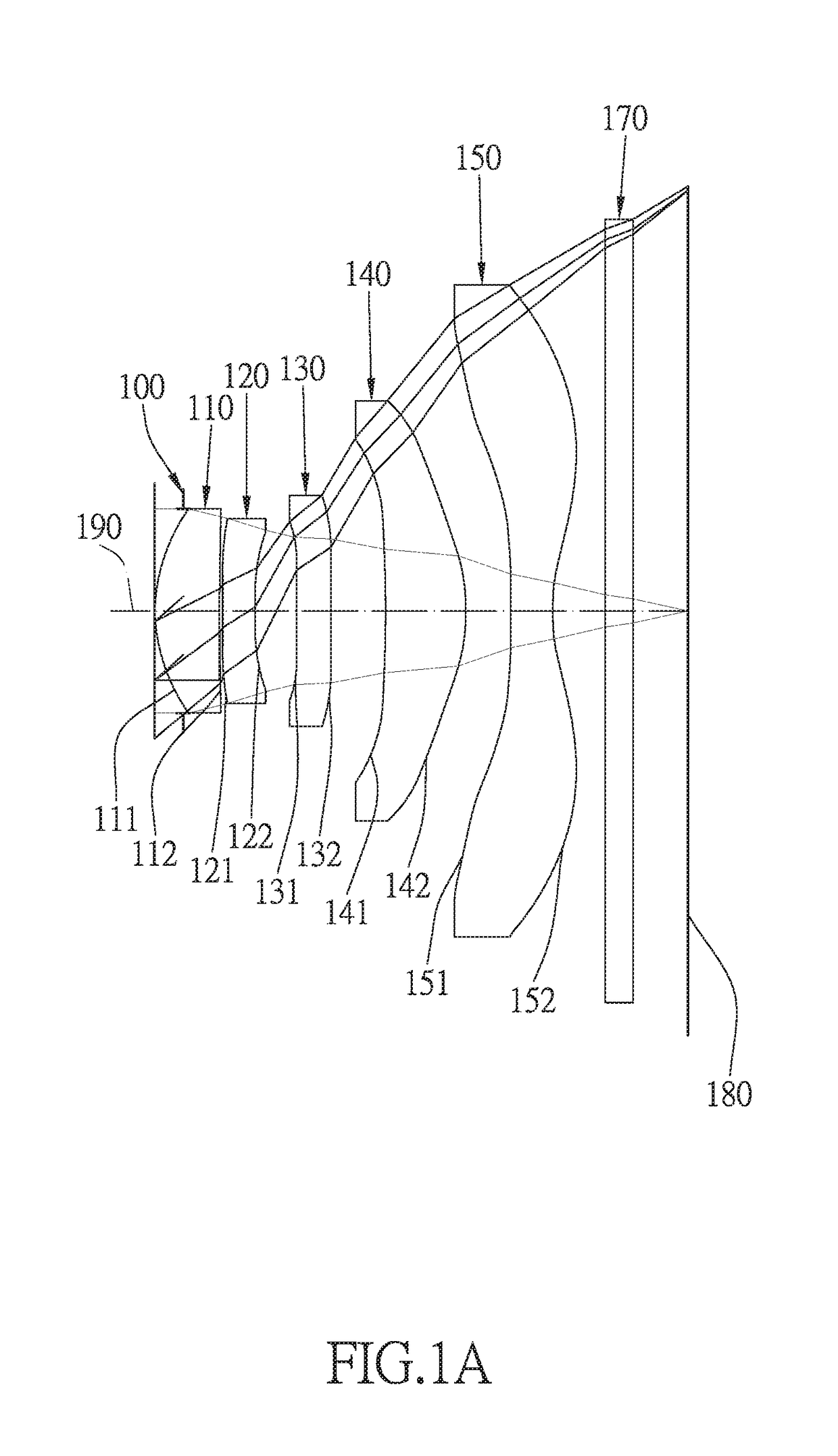
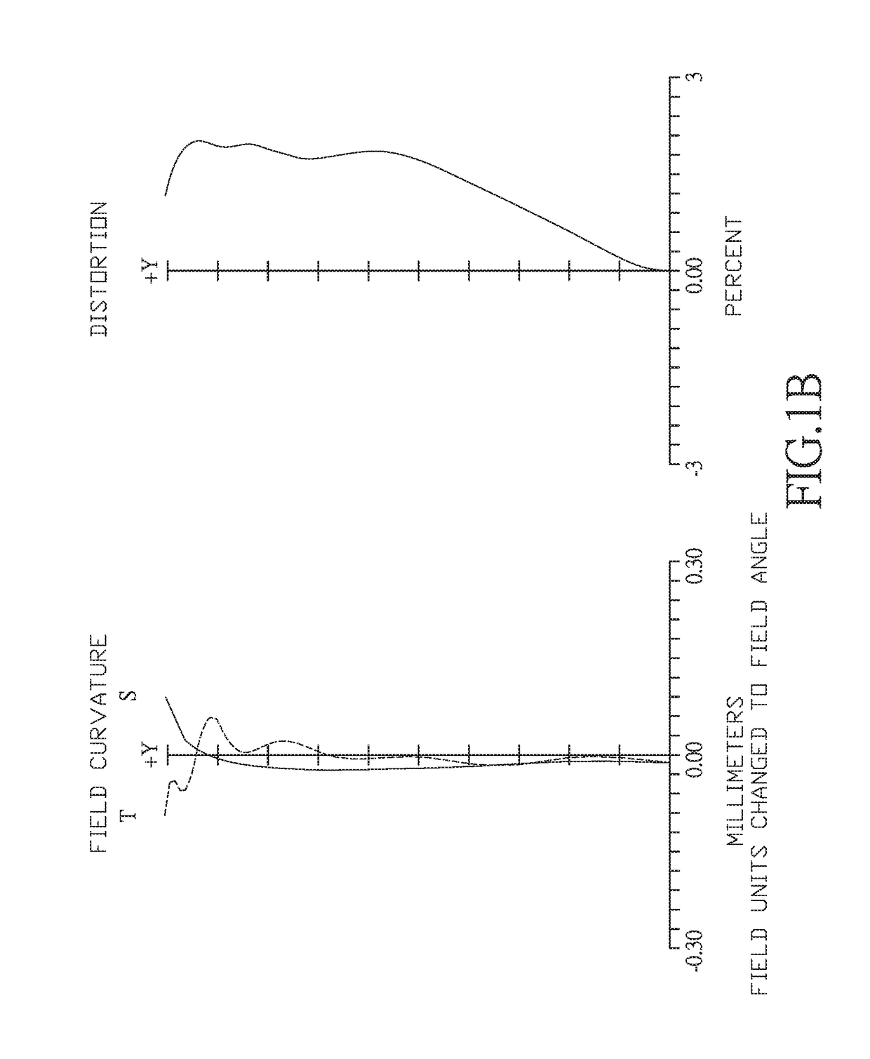
[0045]In the first embodiment of the present five-piece optical imaging lens, the focal length of the optical imaging lens is f, the f-number of the optical imaging lens is Fno, the maximal field of view of the optical imaging lens is FOV, and the following conditions are satisfied: f=3.38 mm; Fno=2.2; and FOV=84 degrees.
[0046]In th...
second embodiment
[0073]The detailed optical data of the second embodiment is shown in table 3, and the aspheric surface data is shown in table 4.
TABLE 3Embodiment 2f(focal length) = 3.38 mm, Fno = 2.2, FOV = 83 deg.SurfaceCurvature RadiusThicknessMaterialindexAbbe #Focal length0objectInfinityInfinity1Infinity0.2172stopInfinity−0.217 3lens 11.178(ASP)0.479plastic1.54456.0002.43848.738(ASP)0.0305lens 232.180(ASP)0.235plastic1.65021.400−5.39363.184(ASP)0.3027lens 3−349.718(ASP)0.249plastic1.65021.400−30.868821.541(ASP)0.3989lens 4−6.868(ASP)0.612plastic1.54456.0002.52310−1.184(ASP)0.31411lens 524.842(ASP)0.300plastic1.54456.000−2.096121.090(ASP)0.36313IR-filterInfinity0.210glass1.51764.167—14Infinity0.42515image planeInfinityInfinity
TABLE 4Aspheric Coefficientssurface34567K:−7.6371E+001.1914E+02−1.9960E+02 1.1417E+01−2.0000E+02A: 5.5787E−01−2.0178E−01 −8.8950E−02 2.7029E−02−2.9195E−01B:−9.3531E−01−3.6320E−01 1.8722E−01 5.6596E−01−2.4059E−01C: 1.4911E+006.1042E+00 4.0242E+00−1.2911E+00 1.5911E+00D:−1.6...
third embodiment
[0083]The detailed optical data of the third embodiment is shown in table 5, and the aspheric surface data is shown in table 6.
TABLE 5Embodiment 3f(focal length) = 3.35 mm, Fno = 2.2, FOV = 84 deg.SurfaceCurvature RadiusThicknessMaterialindexAbbe #Focal length0objectInfinityInfinity1Infinity0.1602stopInfinity−0.160 3lens 11.172(ASP)0.479plastic1.54456.0002.42048.872(ASP)0.0305lens 238.922(ASP)0.195plastic1.65021.400−5.32163.202(ASP)0.2957lens 3−29.017(ASP)0.290plastic1.65021.400−31.372871.504(ASP)0.4919lens 4−9.666(ASP)0.586plastic1.54456.0001.88310−0.950(ASP)0.20511lens 5−4.597(ASP)0.330plastic1.54456.000−1.580121.090(ASP)0.38013IR-filterInfinity0.210glass1.51764.167—14Infinity0.42515image planeInfinityInfinity
TABLE 6Aspheric Coefficientssurface34567K:−7.3032E+00 1.0830E+02−7.8511E+01 1.3248E+01 1.3955E+02A: 5.4995E−01−2.3465E−01−1.0387E−01 1.4748E−02−3.1986E−01B:−9.5530E−01−2.2344E−01 3.5714E−01 7.6289E−01 5.9614E−02C: 1.7778E+00 6.7115E+00 4.9115E+00−1.9302E+00 4.2589E−01D:−2.683...
PUM
 Abstract
Description
Claims
Application Information
 - R&D
- Intellectual Property
- Life Sciences
- Materials
- Tech Scout
- Unparalleled Data Quality
- Higher Quality Content
- 60% Fewer Hallucinations
Browse by: Latest US Patents, China's latest patents, Technical Efficacy Thesaurus, Application Domain, Technology Topic, Popular Technical Reports.
© 2025 PatSnap. All rights reserved.Legal|Privacy policy|Modern Slavery Act Transparency Statement|Sitemap|About US| Contact US: help@patsnap.com


