Thermal mapping catheter
a catheter and thermal imaging technology, applied in the field of thermal imaging catheters, can solve the problems of exacerbated problems, difficult to maintain good electrical contact with cardiac tissue, and difficult to keep adequate contact between electrodes and tissue for a sufficient length of tim
- Summary
- Abstract
- Description
- Claims
- Application Information
AI Technical Summary
Benefits of technology
Problems solved by technology
Method used
Image

Examples
second embodiment
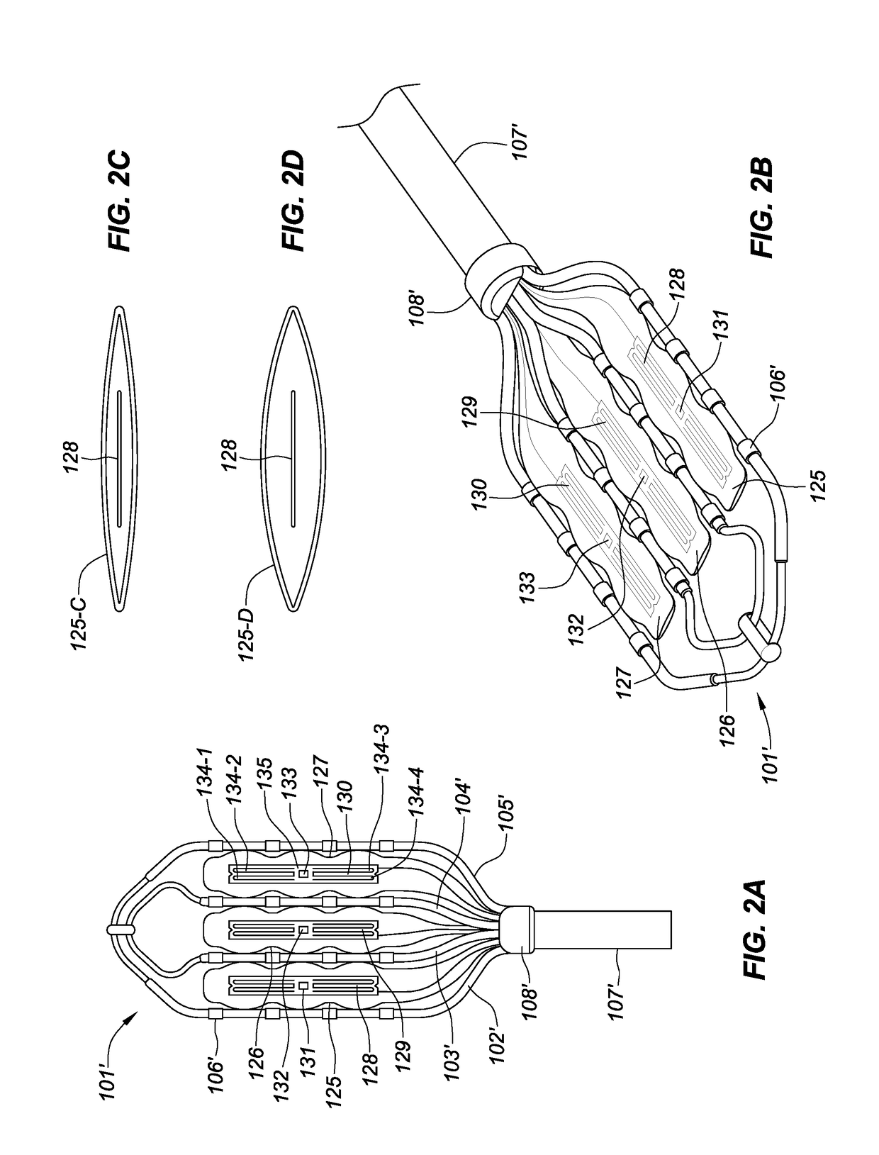
[0048]FIG. 2A is a top view of a thermal mapping catheter 101′. The thermal mapping catheter 101′ can include longitudinally extending arms 102′, 103′, 104′, 105′, which can form the flexible framework on which ring electrodes 106′ are carried. The thermal mapping catheter 101′ can also include the catheter shaft 107′ and the connector 108′. The thermal mapping catheter 101′ can include fluid sacs 125, 126, 127, as discussed in relation to FIG. 1A. In some embodiments, the fluid sacs 125, 126, 127 can be individual fluid sacs (i.e., not connected to one another). For example, the fluid sacs 125, 127 can be separate from one another and not in fluid communication with one another via the fluid conduit 118, as discussed in relation to FIG. 1A.
[0049]In some embodiments, the thermal mapping catheter 101′ can include flexible circuits 128, 129, 130, which can serve as heating elements to heat the fluid. In some embodiments, the flexible circuits can include temperatures sensors 131, 132,...
third embodiment
[0053]FIG. 3A is a top view of the thermal mapping catheter 101″. The thermal mapping catheter 101″ can include longitudinally extending arms 102″, 103″, 104″, 105″, which can form the flexible framework on which ring electrodes 106″ are carried. The thermal mapping catheter 101″ can also include the catheter shaft 107″ and the connector 108″. The thermal mapping catheter 101″ can include fluid sacs 146, 147, 148, as discussed in relation to FIG. 1A. In some embodiments, the thermal mapping catheter 101″ can include a thin film heating element 143, 144, 145. In an example, the thin film heating element can include a thin film layer, which in some embodiments can be a layer formed from silicon. In some embodiments, a conductive layer can be disposed on the thin film, which can form the heating element. For example, the conductive layer can be deposited on the thin film via a deposition process, such as thermal deposition and / or chemical deposition. In some embodiments, the conductive...
fourth embodiment
[0060]FIG. 4 is a top view of a thermal mapping catheter. The thermal mapping catheter 101′″ can include longitudinally extending arms 102′″, 103′″, 104′″, 105′″, which can form the flexible framework on which ring electrodes 106′″ are carried. The thermal mapping catheter 101′″ can also include the catheter shaft 107′″ and the connector 108′″. In some embodiments, the catheter shaft 107′″ can include one or more ring electrodes 167. The thermal mapping catheter 101′″ can include fluid sacs 158, 159, 160, as discussed in relation to FIG. 1A.
[0061]In some embodiments, each fluid sac 158, 159, 160 can include a heating and temperature sensing assembly. In an example, each heating and temperature sensing assembly can include a proximal electrode 156 and a distal electrode 155, which use a bipolar radio frequency (RF) technique to heat the fluid included in each fluid sac 158, 159, 160. In an example, a temperature sensor 157 can be mounted between the proximal electrode 156 and the dis...
PUM
 Abstract
Description
Claims
Application Information
 - R&D
- Intellectual Property
- Life Sciences
- Materials
- Tech Scout
- Unparalleled Data Quality
- Higher Quality Content
- 60% Fewer Hallucinations
Browse by: Latest US Patents, China's latest patents, Technical Efficacy Thesaurus, Application Domain, Technology Topic, Popular Technical Reports.
© 2025 PatSnap. All rights reserved.Legal|Privacy policy|Modern Slavery Act Transparency Statement|Sitemap|About US| Contact US: help@patsnap.com