Impeller with removable and replaceable vanes for centrifugal pump
- Summary
- Abstract
- Description
- Claims
- Application Information
AI Technical Summary
Benefits of technology
Problems solved by technology
Method used
Image
Examples
Embodiment Construction
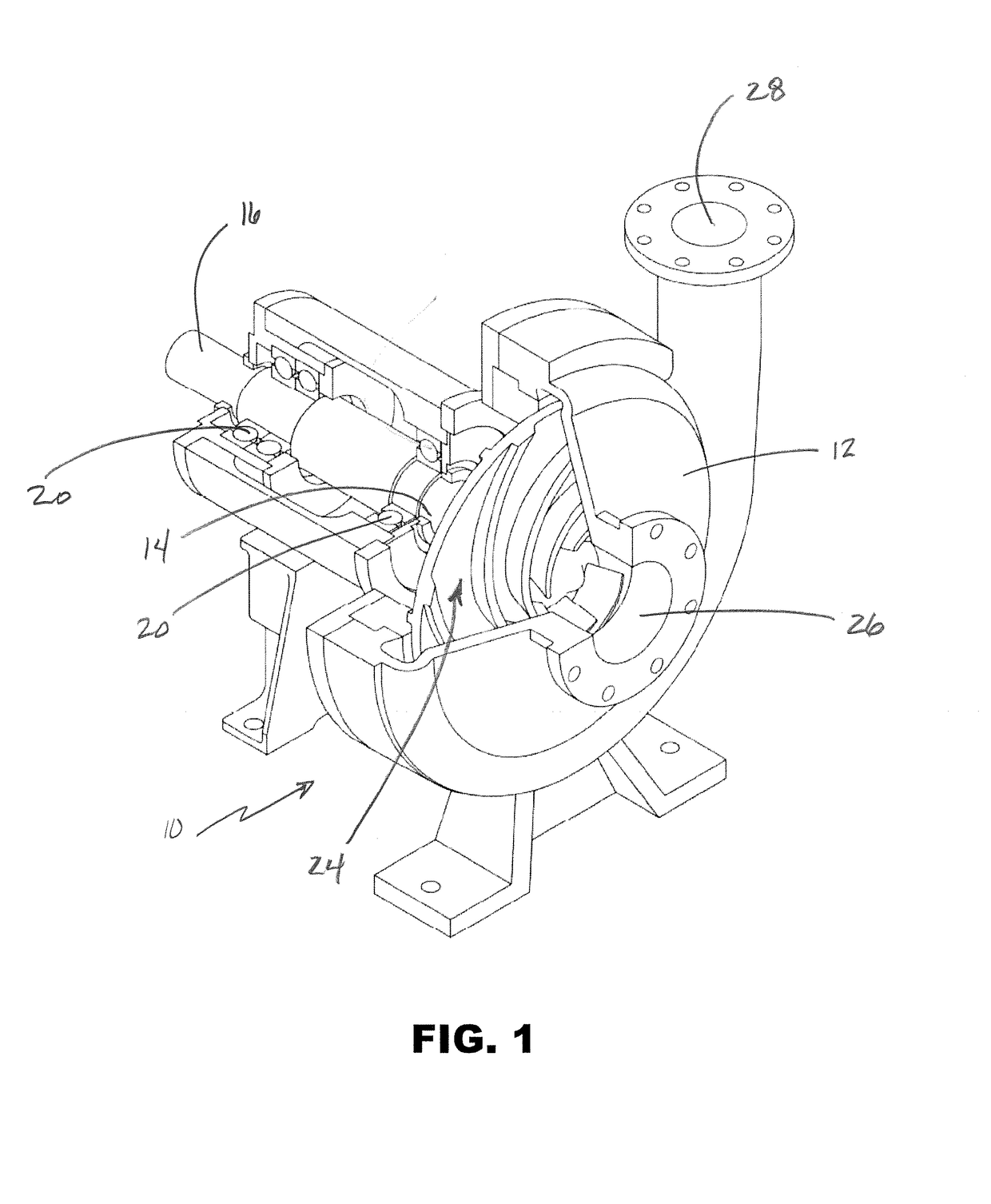
[0072]Turning to FIG. 1, one embodiment of a centrifugal pump 10 is illustrated with a portion of the casing 12 removed to reveal internal structures. The casing has a first opening 14 to receive a rotary shaft 16. The shaft is rotated by a motor (not shown) and supported by bearings 20. An impeller 22 is affixed to the end of the shaft 16 and is positioned in an interior chamber 24 of the casing 12. The casing further includes an intake opening 26 that is in fluid communication with the chamber 24 and a discharge port 28 which is also in fluid communication with the chamber 24. In operation, the motor rotates the shaft 16 and impeller 22. Rotation of the impeller 22 causes fluid to be drawn into the chamber 24 through the intake opening 26 and expelled out of the discharge port 28.
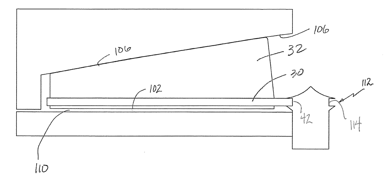
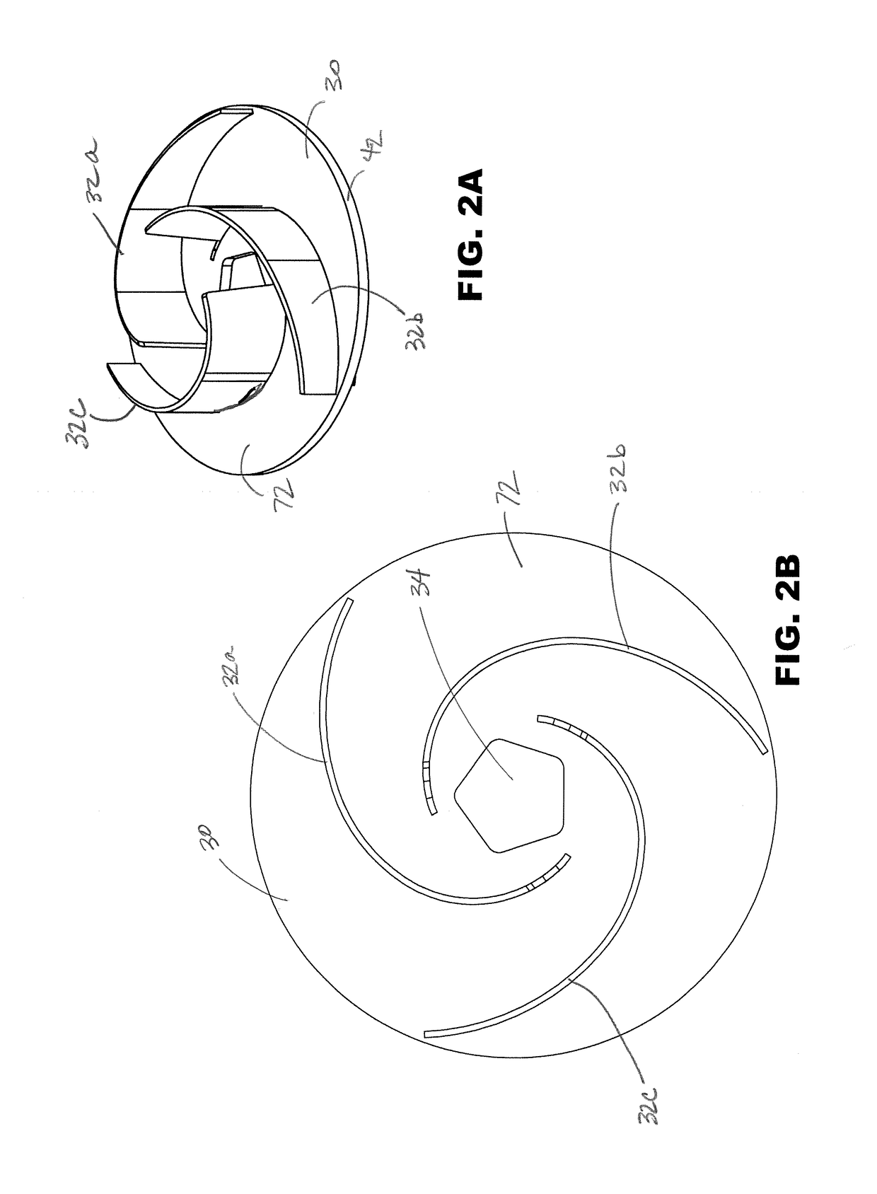
[0073]FIGS. 2A and 2B illustrate one embodiment of an impeller made according to aspects of the present disclosure. The impeller comprises a back plate 30 and three curved vanes 32a-32c. The vanes 32a-32c...
PUM
 Abstract
Description
Claims
Application Information
 - R&D
- Intellectual Property
- Life Sciences
- Materials
- Tech Scout
- Unparalleled Data Quality
- Higher Quality Content
- 60% Fewer Hallucinations
Browse by: Latest US Patents, China's latest patents, Technical Efficacy Thesaurus, Application Domain, Technology Topic, Popular Technical Reports.
© 2025 PatSnap. All rights reserved.Legal|Privacy policy|Modern Slavery Act Transparency Statement|Sitemap|About US| Contact US: help@patsnap.com


