Eureka AIR delivers breakthrough ideas for toughest innovation challenges, trusted by R&D personnel around the world.

Wall panel damping device

a damping device and wall panel technology, applied in the direction of shockproofing, building components, building construction, etc., can solve the problems of inability to achieve efficient control effect, friction wall dampers are not suitable for alleviating wind-induced or low-intensity earthquake excited structural responses, and the effect of vibrating stops

Inactive Publication Date: 2017-12-21
UNIVERSITI PUTRA MALAYSIA
View PDF10 Cites 6 Cited by
  • Summary
  • Abstract
  • Description
  • Claims
  • Application Information

AI Technical Summary

Benefits of technology

The present invention provides a viscoelastic damping device that uses rubber elements and can provide damping against multidirectional loads. It can also be used as a wall panel in steel and reinforced concrete structures. The device comprises a pair of symmetrically opposing surfaces with alternating layers of viscoelastic and rigid planar members. It is covered with a pair of face plates that overlay the assembly. The technical effect is that the invention provides a viscoelastic damping device that can provide damping against in-plane shear force and out-of-plane force resistance loads, and can be used as a wall panel in steel and reinforced concrete structures.

Problems solved by technology

All structures have inherent damping which causes them to stop vibrating.
However, owing to the inherent characteristics of friction dampers, the friction wall damper is not suitable for alleviating wind-induced or low intensity earthquake excited structural responses.
Accordingly, thus far, an efficient control effect cannot always be achieved.

Method used


Image

  • Wall panel damping device
  • Wall panel damping device
  • Wall panel damping device

Examples


Embodiment Construction

[0039]The detailed description set forth below in connection with the appended drawings is intended as a description of an exemplary embodiment and is not intended to represent the only form in which the embodiment may be constructed and / or utilized, The description sets forth the functions and the sequence for constructing the exemplary embodiment. However, it is to be understood that the same or equivalent functions and sequences may be accomplished by different embodiments that are also intended to be encompassed within the scope of this disclosure.

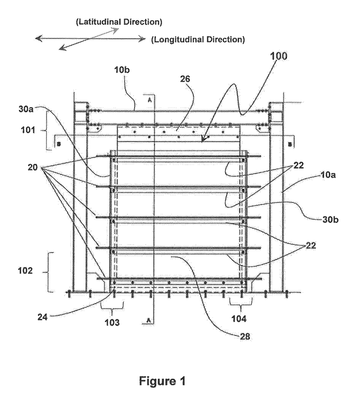
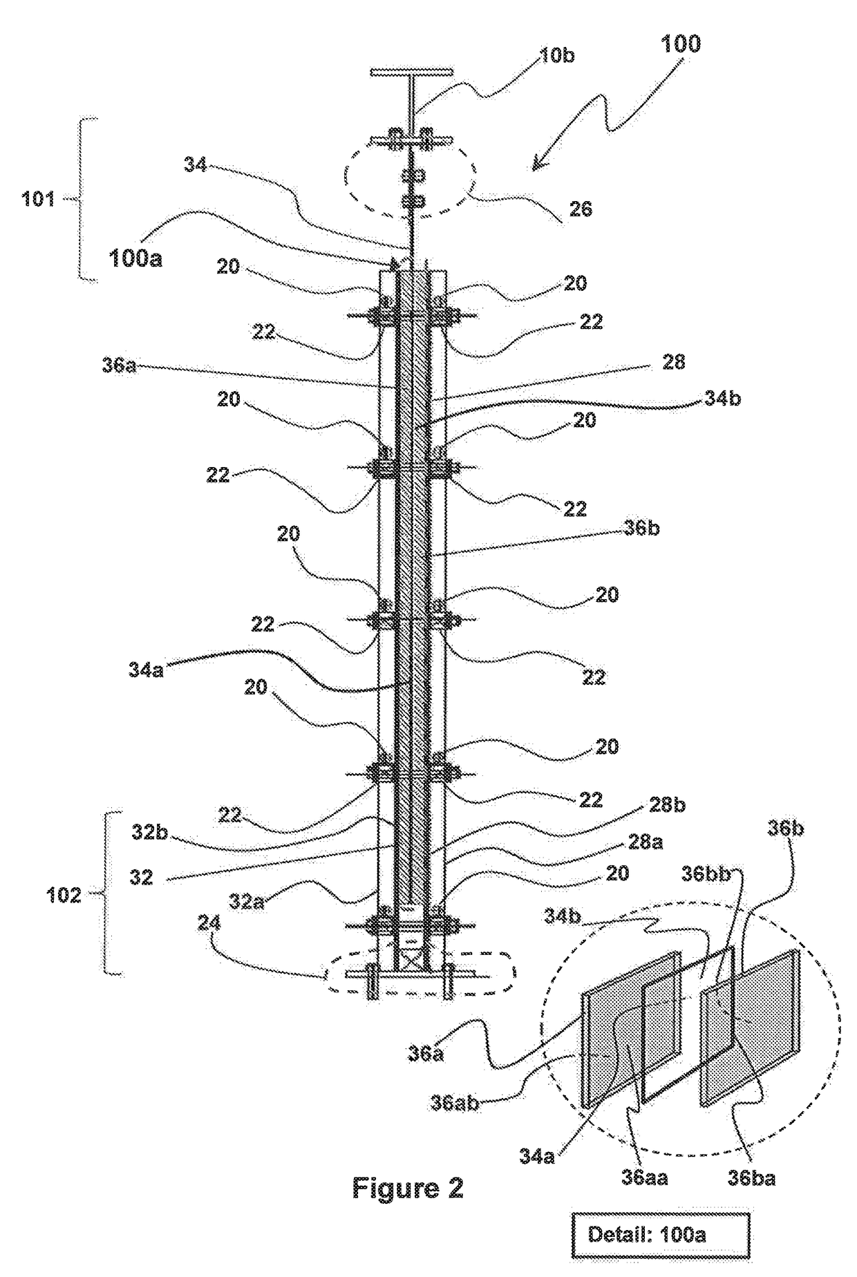
[0040]With reference to the appended FIGS. 1 to 8, a preferable embodiment of the wall panel damping device of the present invention will now be described. With reference to FIG. 1, there is shown a side elevation view of a viscoelastic wall panel damping device 100 in accordance to a preferable embodiment of the present invention. FIG. 2, as mentioned in a preceding section of this document illustrates a cross-sectional view taken alo...


PUM


Abstract

The present invention provides a viscoelastic wall panel damping device (100) that provides damping against multidirectional reacting dynamic loads that include in-plane shear force resistance and out of plane force resistance. The viscoelastic wall panel damping device (100) of the present invention, including an assembly (100a) having a pair of symmetrically opposing surfaces formed by a pair of damping element planar members (36a, 38b) that sandwiches a rigid planar member (34), The assembly (100a) being over-laid by a pair of face plates (28, 32), a proximal face plate (28) and a distal face plate (32). Aforementioned pair of face plates (28, 32) and the rigid planar member (34) of the assembly (100a) having a plurality of vertically oriented stiffener members (33) comprising of vertically oriented welded strips (33a) of steel disposed with stiffener elements (33b) at spatial intervals along the length of said welded strips of steel (33a). Aforementioned pair of face plates (28, 32) further being disposed at respective outer surfaces (28a, 32a) with a plurality of horizontal stiffener members (22).

Description

[0001]The present invention relates to the broad field of vibration damping. More particularly, the present invention relates to a damping device for use in structures such as steel and reinforced concrete buildings that are subjected to dynamic loads. Most particularly, the present invention relates to a wall panel damping device.BACKGROUND TO THE INVENTION[0002]It is known that increasing the damping in a structure will result in the improvement in the response and performance of a structure under earthquake vibrations, wind forces or any structural stability hazard of similar nature. All structures have inherent damping which causes them to stop vibrating. This damping is the result of internal factors such as damping of the material of the structure, the movement in the connections or external factors such as air resistance. Typically damping in a structure can approximately vary between 2% to 7%. With the use supplemental dampers, damping can be increased substantially to a des...

Claims


Application Information

Patent Timeline
Patent Type & Authority Applications(United States)
IPC IPC(8): E04B1/98E04B1/24E04B1/61E04H9/02
CPCE04B1/98E04B1/61E04B1/24E04H9/022
Inventor HEJAZI, FARZADJAAFAR, MOHD SALEHMOHD ZAIN, MOHD AZMI
Owner UNIVERSITI PUTRA MALAYSIA
Why Eureka
Eureka Blog
Learn More