
Battery pack and vehicle equipped with same

Active Publication Date: 2017-12-07
SANYO ELECTRIC CO LTD
View PDF2 Cites 29 Cited by
  • Summary
  • Abstract
  • Description
  • Claims
  • Application Information

AI Technical Summary

Benefits of technology

The invention relates to a battery pack with increased structural stability and reduced expansion. It includes an end plate with first and second members that work together to absorb the force generated by the cell stack. This reduces the risk of damage to the battery from excessive expansion and ensures a firm connection between the end plate and the battery. The use of rivets, particularly blind rivets, allows for a larger caulked portion and a stronger connection. Overall, the battery pack is designed to be sturdy and dependable.

Problems solved by technology

That is because heavy end plates increase the weight of the battery pack and thick end plates increase the size of the battery pack.
However, a resin-made end plate can be made lightweight but cannot obtain a high rigidity.
Disadvantageously, a metal-made end plate can obtain a high rigidity but cannot be made lightweight.

Method used


Image

  • Battery pack and vehicle equipped with same
  • Battery pack and vehicle equipped with same
  • Battery pack and vehicle equipped with same

Examples


Embodiment Construction

)

[0054]Hereinafter, examples of the present invention are described with reference to the accompanying drawings. The following examples show battery packs for embodying the technical ideas of the present invention. The present invention is not limited to the following battery packs. In the present invention, members shown in the scope of claims are not limited to the members of the examples.

[0055]A battery pack shown in the following example is optimum for a power source of an electric vehicle such as a hybrid car or plug-in hybrid car that travels using both an engine and a motor, an electric car travelling using only a motor, or an electric motorcycle travelling using a motor. However, the battery pack of the present invention is available also for applications requiring a large output other than the electric vehicle, for example, is available as a power source for an electric storage device.

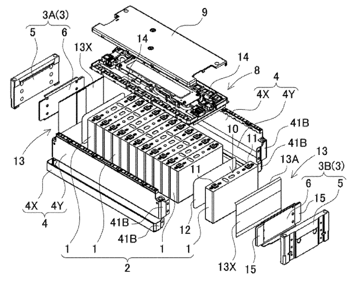
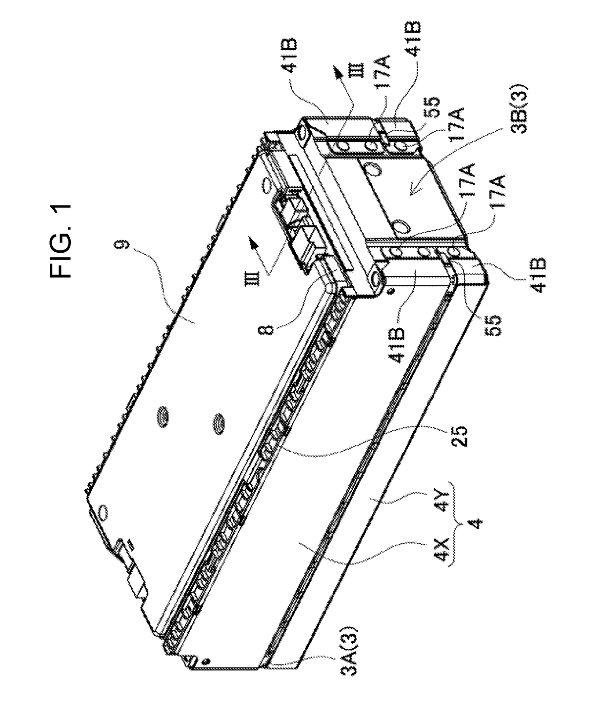
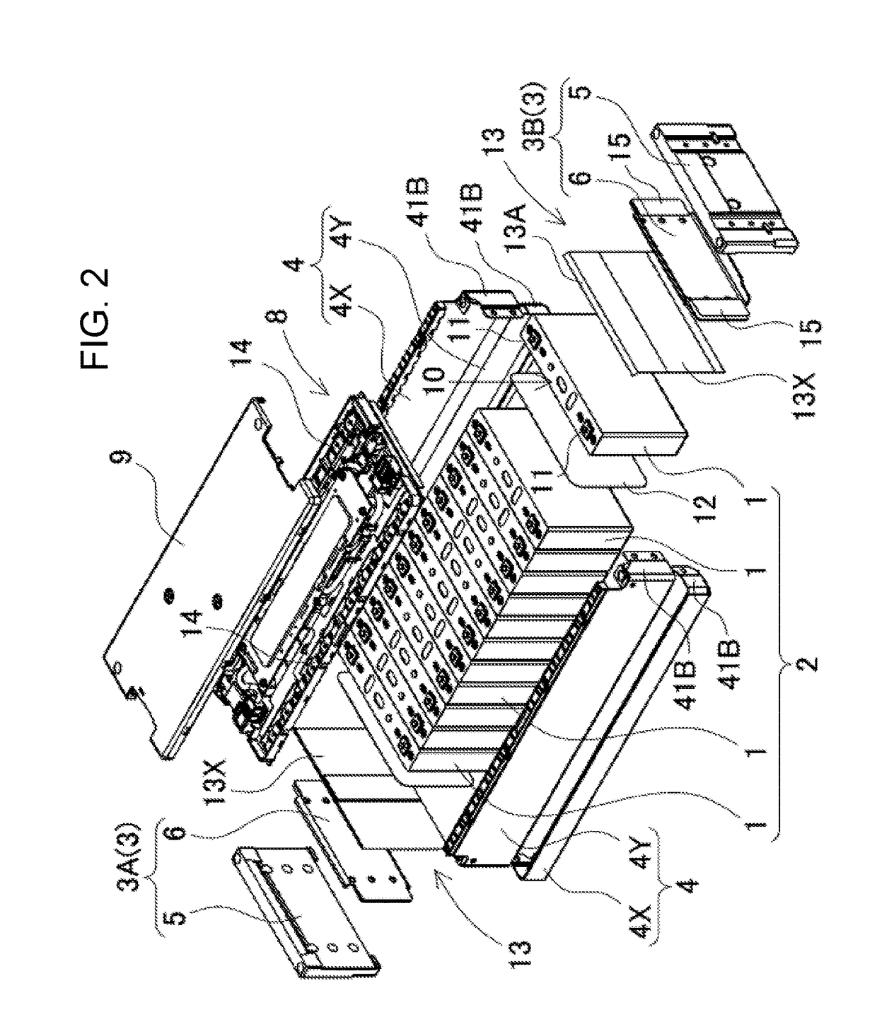
[0056]A battery pack shown in FIG. 1 and FIG. 2 includes the following elements:

[0057]cell...


PUM


Abstract

A battery pack including a lightweight and high-rigidity end plate is provided. The battery pack includes: cell stacked body including a plurality of stacked rectangular cells; first end plate disposed at one end of cell stacked body in the stacking direction of rectangular cells; second end plate disposed at the other end of cell stacked body; and connection member connected to first end plate and second end plate. At least one of first end plate and second end plate includes first member made of a first metal material and second member made of a second metal material different from the first metal material. First member and second member are stacked in the stacking direction of rectangular cells. The rigidity of the second metal material is higher than that of the first metal material. The specific gravity of the first metal material is lower than that of the second metal material.

Description

TECHNICAL FIELD[0001]The present invention relates to a battery pack in which a plurality of cells are stacked and endplates are disposed at the opposite ends, and to a vehicle equipped with the battery pack.BACKGROUND ART[0002]In a battery pack including a plurality of stacked cells, the output voltage can be increased by interconnecting the cells in series, the output current can be increased by interconnecting the cells in parallel. Therefore, the battery pack having this structure is used as a power source of a large output and a large capacity, for example, as a power source device for a vehicle. In the battery pack having this structure, a cell stacked body is grasped with end plates at its opposite ends and is firmly fixed. The end plates fixed in a state where the cells are pressurized require a robust structure. When the cells swell due to the charge and discharge, a high pressure acts on the end plates. The end plates not only must have a high rigidity, but also must be li...

Claims


Application Information

Patent Timeline
IPC IPC(8): H01M2/10H01M50/209H01M50/224H01M50/233H01M50/236H01M50/289
CPCH01M2220/20H01M2/1077Y02E60/10H01M50/224H01M50/236H01M50/209H01M50/233H01M50/289
Inventor NAGANE, TAKESHIHIRAKAWA, YASUSHI
Owner SANYO ELECTRIC CO LTD
Learn More