
A sensor device, in particular a pressure sensor

a sensor device and pressure sensor technology, applied in the direction of fluid pressure measurement by mechanical elements, fluid pressure measurement using elastically deformable gauges, instruments, etc., can solve the problems of inability to reliably and/or produce time and costs, freeze of fluid being measured, and increase in volume, so as to improve reliability and economic advantages, the effect of simple and more economical production

Active Publication Date: 2017-12-07
ELTEK
View PDF6 Cites 8 Cited by
  • Summary
  • Abstract
  • Description
  • Claims
  • Application Information

AI Technical Summary

Benefits of technology

The present invention aims to provide a better pressure-sensor device that is simpler and more cost-effective to produce. It also improves reliability compared to previous devices.

Problems solved by technology

In certain applications, the devices of the type referred to operate in conditions of very low temperature, and it may occasionally happen that the fluid being measured freezes, thus increasing in volume.
The pressure-sensor devices proposed in the prior document referred to are on average efficient from the functional standpoint, but still present some drawbacks in terms of reliability and / or production times and costs, which it would be desirable to reduce.

Method used


Image

  • A sensor device, in particular a pressure sensor
  • A sensor device, in particular a pressure sensor
  • A sensor device, in particular a pressure sensor

Examples


Embodiment Construction

[0037]Reference to “an embodiment” or “one embodiment” in the framework of the present description is intended to indicate that a particular configuration, structure, or characteristic described in relation to the embodiment is comprised in at least one embodiment. Hence, phrases such as “in an embodiment” or “in one embodiment” and the like that may be present in various points of this description do not necessarily refer to one and the same embodiment, but may, instead, refer to different embodiments. Furthermore, particular conformations, structures, or characteristics defined in this description may be combined in any adequate way in one or more embodiments, even different from the ones represented. The reference numbers and spatial references (such as “upper”, “lower”, etc.) are used herein only for convenience and hence do not limit the scope of protection or the scope of the embodiments. In the figures, the same reference numbers are used to designate elements that are simila...


PUM

PropertyMeasurementUnit
bulk modulusaaaaaaaaaa

Abstract

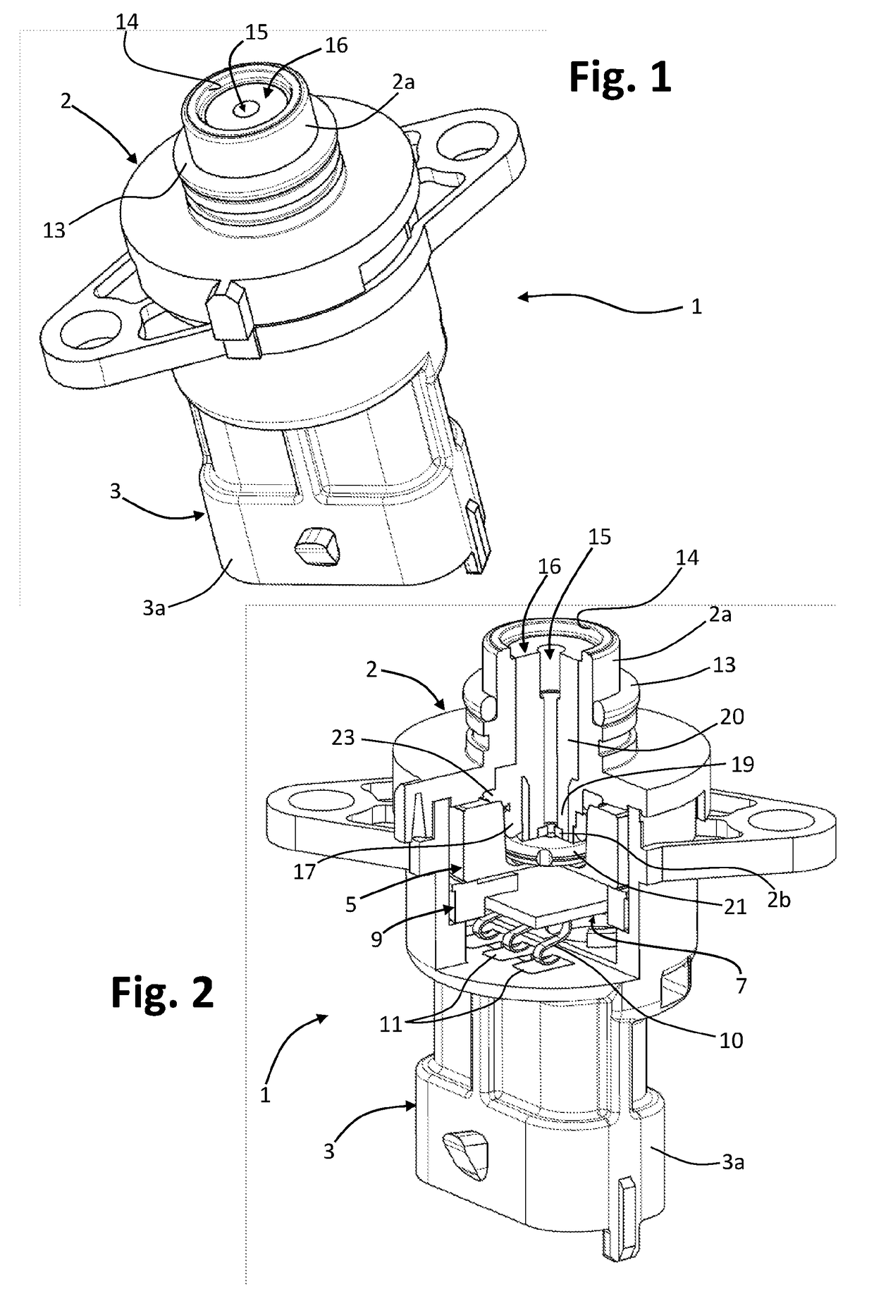
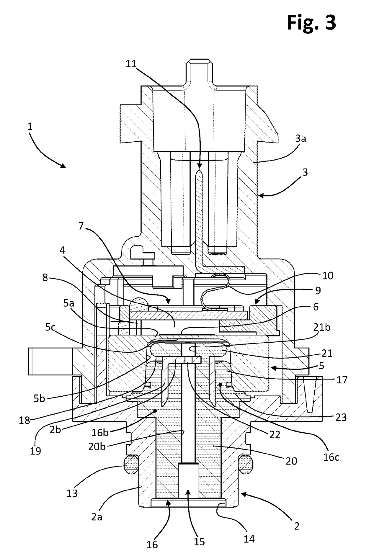
A pressure-sensor device (1) has: —a component sensitive to pressure, comprising a sensor body (5), with an elastically deformable membrane part (5a), and at least one detection element (6) for detecting a deformation of the membrane (5a); —a structure (2, 3) for housing or supporting the pressure-sensitive component, having at least one passageway (15) for a fluid the pressure of which is to be detected, the housing or supporting structure (2, 3) comprising a supporting body (2) with respect to which the sensor body (5) is positioned in such a way that its membrane part (5a) is exposed to the fluid coming out of the passageway (15), the supporting body (2) having a hydraulic-connection portion (2a) and a duct (14) that extends from the hydraulic-connection portion (2a); —at least one elastically deformable body (16), formed with one or more elastically deformable or compressible materials, comprising at least one from among: —a compressible compensation element (20, 21), configured for compensating any possible variations in volume of the fluid; —a sealing element (13, 17); configured for providing a seal with respect to at least one of the housing or supporting structure (2, 3), and the sensor body (5); and—a supporting element (23), configured for supporting or positioning the sensor body (5) with respect to the housing or supporting structure (2, 3). At least one from among the compressible compensation element (16), the sealing element (13, 17) and the supporting element (23) is overmoulded on at least one of the housing or sup porting structure (2, 3) and the sensor body (5).

Description

FIELD OF THE INVENTION[0001]The present invention relates to sensor devices and has been developed with particular reference to sensor devices having a body comprising an elastically deformable membrane, associated to which is an element sensitive to deformation of the membrane. The invention finds preferred application in the sector of pressure-sensor devices.PRIOR ART[0002]A sensor device having the characteristics specified in the preamble of claim 1 is known from the document No. WO2008 / 078184 A2 filed in the name of the present applicant.[0003]The above document describes a pressure-sensor device the sensitive component of which has a sensor body with a blind cavity, the bottom of which is formed by a membrane part. The membrane part is elastically deformable, and associated thereto is a sensing element, such as a bridge of resistive or piezoresistive elements. The device has a casing made up of a number of parts, amongst which a body for supporting the sensor body. The support...

Claims


Application Information

Patent Timeline
Patent Type & Authority Applications(United States)
IPC IPC(8): G01L7/08G01L19/14
CPCG01L7/082G01L19/143G01L7/088G01L19/0038G01L19/0672
Inventor GADINI, COSTANZOBIGLIATI, MARCO
Owner ELTEK
Learn More