Method and mechanism for interactively governing trigger movement and regulating the cyclic firing rate of firearms

a technology of cyclic firing rate and trigger movement, applied in the field of firearms, can solve the problems of increasing the cost and complexity of manufacturing and inventory control, the secondary type of mechanism of the mechanism of the mechanism of the mechanism of the secondary type of the mechanism, and the difficulty of adjusting the trigger position, etc., to achieve enhanced trigger feel and/or trigger tactile sense, and improve the operational management of the firearm trigger movement.

Inactive Publication Date: 2017-12-07
ANGELIS JOHNS JEFF
View PDF0 Cites 3 Cited by
  • Summary
  • Abstract
  • Description
  • Claims
  • Application Information

AI Technical Summary

Benefits of technology

[0051]It is therefore, accordingly, a primary objective of the instant novel invention to advantageously fulfill the foregoing needs while providing an improved innovative utility and a unique operational method and mechanism designed to functionally enable the firearm operator to accurately, intuitively, and interactively regulate the firearm trigger discharge and reset positions and by that means produce a more precise single discharge event and / or, advantageously, a variable sequential cyclic firing rate for a diversity of firearms.
[0052]Several inherent advantages that the current invention presents are referenced favorably below in comparative benefit and differentiation from the prior art. Although the following listed advantages represent a selection of propitious solutions to a number of previously mentioned and existing limitations of the prior art, as remarked above, there are other benefits that the immediate invention presents which will become even more obvious and apparent in view of the forthcoming supplementary information, specifications, and inclusionary documentation, thereby demonstrating the present inventions objectives to be purposeful accomplished by the various means hereinafter described.
[0053]The preferred apparatus, embodying stylistic illustrative concepts of the present invention, consists in its most basic structure of an interfacing controller mechanism which effects improved operational management of the firearm trigger movement. The controller in this instance having an elliptical forward region providing a variable tangential contact surface which is contiguous with the rear region of the firearms trigger, said trigger being under demonstrated proximate tension having been manually rotated laterally into contact with the controllers elliptical forward region by force of sustained rearward pressure actively applied by the operators trigger finger upon the trigger. The trigger formerly having been at rest in its normal and stationary most forward position and, while in that expressed position, out of contact with the controllers elliptical forward region. The controller structure in this expression having a most rearward conformational surface region in alignment with the innermost and / or upper-innermost region of the operators firing hand.

Problems solved by technology

This forward pivoting of what amounts to a manually engaged secondary type trigger within the original trigger housing is antithetical to the normal method that shooters use to discharge a firearm, and the above described prior art structural spring and trigger biasing mechanism and apparatus having a secondary type trigger mechanism is somewhat operationally awkward and problematic, especially when examined in consideration of the subsequent narrative and when reviewed in further comparison to the following referenced prior art and the present novel invention.
Beyond the above issues, the Akins '918 prior art system and design requires a significant number of moving and / or ancillary non Original Equipment Manufacturer (OEM) parts, including supplements involving the primary firing unit and the secondary supporting elements, which increases the cost and complexity of manufacturing and inventory control while substantively restricting the application of the Akins '918 system to a relatively limited number and type of firearm.

Method used


Image

  • Method and mechanism for interactively governing trigger movement and regulating the cyclic firing rate of firearms
  • Method and mechanism for interactively governing trigger movement and regulating the cyclic firing rate of firearms
  • Method and mechanism for interactively governing trigger movement and regulating the cyclic firing rate of firearms

Examples


Embodiment Construction

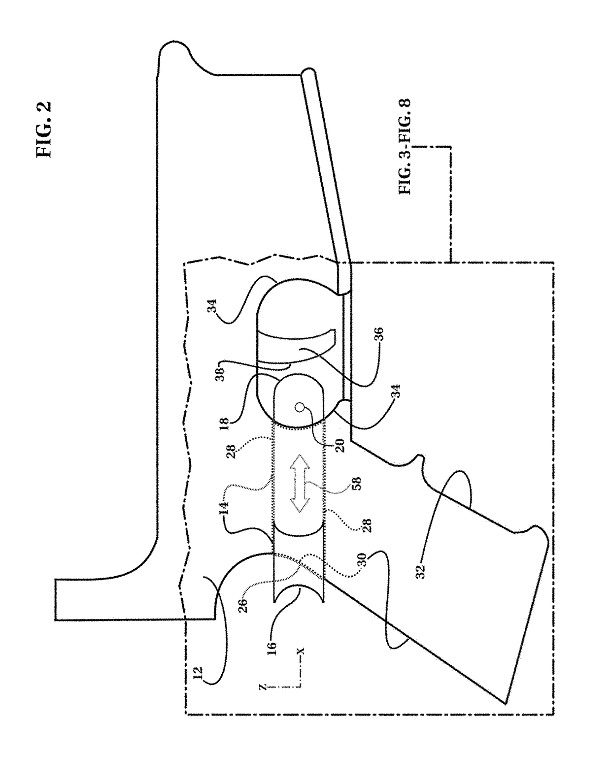
[0098]Referring now to the invention in more detail wherein the figures have like numerals which indicate like or corresponding parts throughout the several views.

[0099]As seen in FIG. 1 on drawing sheet 1 / 18, a serviceable M4 Carbine type firearm 10 is shown schematically in a simplified semitransparent figurative depiction being diagramed in contour outline and perspective view as FIG. 1A.

[0100]In more detail still referring to FIG. 1A, as seen within FIG. 1 on drawing sheet 1 / 18, showing an indicating chain line encompassing in part a figurative one piece lower receiver 12 shown mounted on the M4 Carbine type firearm 10. The figurative one piece lower receiver 12 is linked by single chain line to an enlarged semitransparent perspective view representing the same indicated one piece lower receiver 12 shown as FIG. 1B within the sight region of FIG. 1 as described below. Although the illustrations within FIG. 1 depict a unique one piece lower receiver 12, the majority of AR15 type ...


PUM


Abstract

A controlling device and methodology for firearms interfacing the trigger mechanism, trigger finger, and the innermost and / or upper-innermost region of the firing hand as a means to adaptively govern incremental trigger movement and variable trigger pull force in order to accurately discharge a singular round of ammunition and, in alternative method, adaptively regulate and govern a variable cyclic firing ratio and sequential discharge rate. In use, coinciding contraction of the firing hand and trigger finger bring the controller device in concert with the trigger and innermost region of the firing hand thereby effectively isolating the controller with uniformly balanced isometric tension. Trigger movement and trigger pull force being regulated incrementally by utilization of variable isometric tension applied to the controller between the trigger finger, trigger, and the innermost region of the firing hand.

Description

[0001]The present applications claims priority to the earlier filed provisional application having Ser. No. 62 / 346,289 and hereby incorporates subject matter of the provisional application in its entirety.BACKGROUND OF THE INVENTION[0002]1. Field of the Invention[0003]The present invention relates generally to firearms and more distinctly to an interfacing apparatus and operational method which governs the interaction between the firearms trigger, the operators trigger finger, and the innermost region of the operators firing hand thereby regulating trigger movement and the related discharge of ammunition.[0004]2. Description of Related Prior Art[0005]There have been multifarious types of devices and methods developed in the field of firearms in order to govern the discharge of ammunition which have been generally created in order to initiate a single discharge event or increase the firing rate of firearms especially for semiautomatic firearms, including simple methods such as the co...

Claims


Application Information

Patent Timeline
Patent Type & Authority Applications(United States)
IPC IPC(8): F41A19/09F41A19/16
CPCF41A19/16F41A19/09F41A19/10
Inventor ANGELIS-JOHNS, JEFF
Owner ANGELIS JOHNS JEFF
Why Eureka
Try Eureka