Method for assembling wire harness, interference suppressing member, and wire harness assembly structure

a technology of interference suppressing member and wire harness, which is applied in the direction of insulated conductors, cables, conductors, etc., can solve the problems of increasing the number of components and complication of assembly operations, and achieve the effect of preventing the brack

Active Publication Date: 2017-11-02
AUTONETWORKS TECH LTD +2
View PDF4 Cites 6 Cited by
  • Summary
  • Abstract
  • Description
  • Claims
  • Application Information

AI Technical Summary

Benefits of technology

The patent is about a way to make a wire harness that runs through a vehicle's instrument panel reinforcement. Typically, a separate part called an interference suppressing member is used to prevent the wire harness from hitting the reinforcement during assembly. This new design eliminates the need for the interference suppressing member, which simplifies the assembly process and reduces the number of components needed. Overall, this makes it easier and more efficient to create wire harnesses that pass through reinforcements.

Problems solved by technology

However, the electric wires arranged on the instrument panel reinforcement need to be respectively provided with protection members, and thus an increase in the number of components and complication of the assembly operation are a cause of concern.

Method used


Image

  • Method for assembling wire harness, interference suppressing member, and wire harness assembly structure
  • Method for assembling wire harness, interference suppressing member, and wire harness assembly structure
  • Method for assembling wire harness, interference suppressing member, and wire harness assembly structure

Examples


Embodiment Construction

[0036]Hereinafter, a wire harness assembling method according to an embodiment will be described. The wire harness assembling method according to the embodiment is a method in which an interference suppressing member is attached to a reinforcement (instrument panel reinforcement) that is arranged on a back side of an instrument panel of a vehicle and extends in a width direction of the vehicle, and then a wire harness is arranged thereon.

[0037]The following will describe members that are used in the wire harness assembling method according to the embodiment.

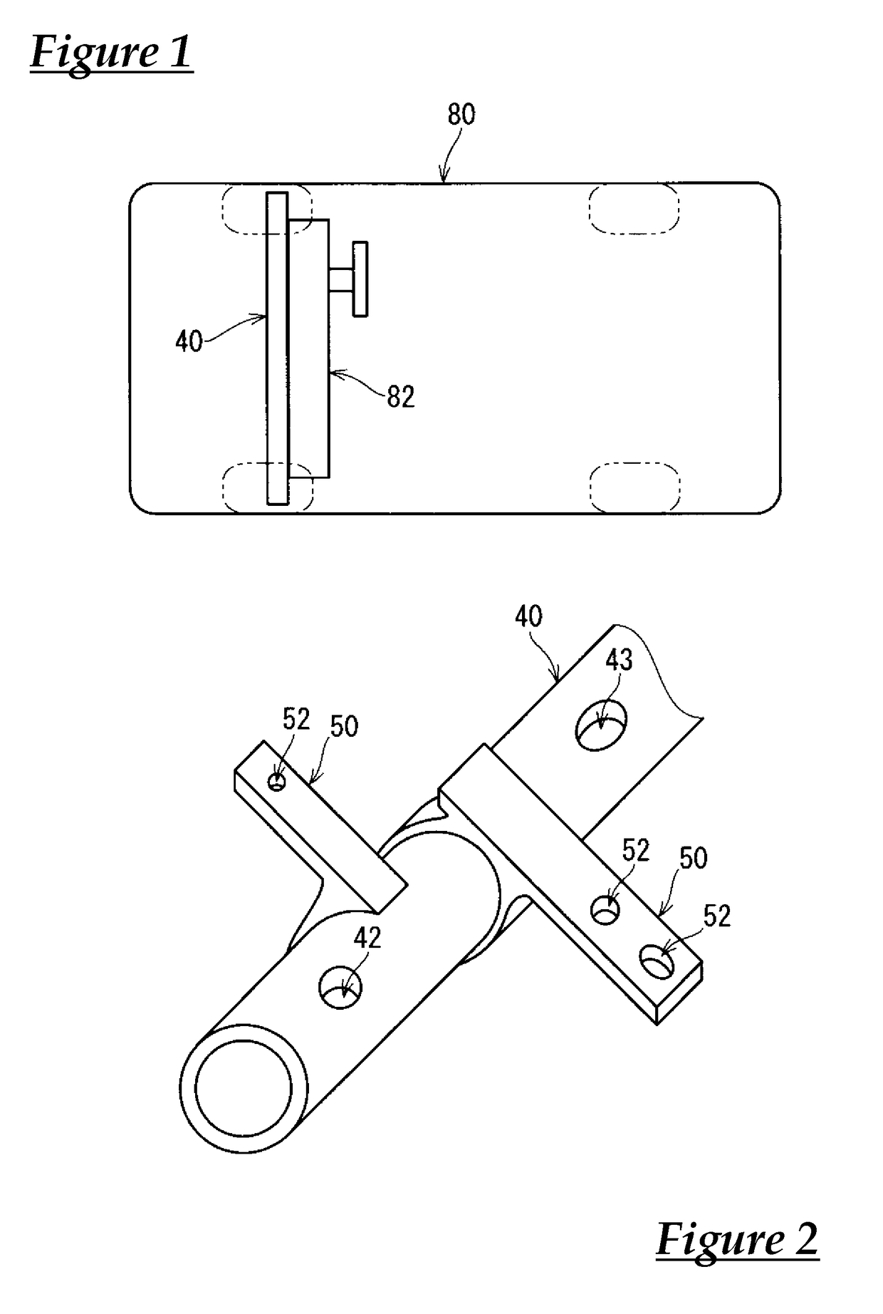
[0038]FIG. 1 illustrates the location in a vehicle 80 at which a reinforcement 40 is arranged. FIG. 2 is a perspective view of the reinforcement 40.

[0039]The reinforcement 40 is arranged on the back side of an instrument panel 82 of the vehicle 80 and extends in the width direction of the vehicle 80. The reinforcement 40 is elongated (here, in the shape of an elongated tube). Here, the reinforcement 40 is provided with attaching ...


PUM

PropertyMeasurementUnit
widthaaaaaaaaaa
timeaaaaaaaaaa
shapeaaaaaaaaaa

Abstract

A wire harness assembling method includes a step (a) of attaching an interference suppressing member to at least a part of an elongated reinforcement, the reinforcement being arranged on a back side of an instrument panel of a vehicle and extending in a width direction of the vehicle; and a step (b) of arranging a wire harness so that the wire harness faces the reinforcement with the interference suppressing member interposed between the wire harness and the reinforcement, the step (b) being performed after the step (a).

Description

CROSS REFERENCE TO RELATED APPLICATIONS[0001]This application claims the priority of Japanese patent application JP2014-227916 filed on Nov. 10, 2014, the entire contents of which are incorporated herein.TECHNICAL FIELD[0002]The present invention relates to a method for assembling a wire harness to a reinforcement that is arranged on the back side of an instrument panel.BACKGROUND ART[0003]Electric wires of wire harnesses that are installed in vehicles such as automobiles may be fixed to a reinforcement (hereinafter, referred to as “instrument panel reinforcement”) that is arranged on the back side of an instrument panel.[0004]For example, a plurality of electric wires that are wound into a bundle with a tape may be fixed to the instrument panel reinforcement using a harness clamp disclosed in Patent Document 1 (JP 2013-118741A). In this case, the tape wound around the electric wires functions as a protection member that prevents the electric wires from coming into contact with the ...

Claims


Application Information

Patent Timeline
Patent Type & Authority Applications(United States)
IPC IPC(8): B60R16/02H01B7/00H02G3/04H02G3/32
CPCB60R16/0215H02G3/32H02G3/0406H01B7/0045F16L3/12H02G3/04H02G3/30
Inventor MIZUNO, HOSEIHIRAI, HIROKITABATA, MASAAKI
Owner AUTONETWORKS TECH LTD
Why Eureka
Try Eureka