Power-source connector including terminal-contact prevention mechanism and power-source connector device including the same

a technology of contact prevention mechanism and power-source connector, which is applied in the direction of coupling contact member, coupling device connection, electrical apparatus, etc., can solve the problems of increasing production cost and complicated operation

Inactive Publication Date: 2017-10-26
HIROSE ELECTRIC GROUP
View PDF24 Cites 3 Cited by
  • Summary
  • Abstract
  • Description
  • Claims
  • Application Information

AI Technical Summary

Benefits of technology

The power-source connector described in this patent can provide a safer and more convenient connection for power sources. It has a terminal that is less likely to be accidentally touched, and it eliminates the need for additional insulating materials. Additionally, the connector has a partitioning member that prevents fingers from touching the contact portion where the electrically conductive member is inserted. Overall, this design reduces the risk of injury and improves the overall user experience.

Problems solved by technology

This configuration renders the operation very complicated and increases production costs.

Method used


Image

  • Power-source connector including terminal-contact prevention mechanism and power-source connector device including the same
  • Power-source connector including terminal-contact prevention mechanism and power-source connector device including the same
  • Power-source connector including terminal-contact prevention mechanism and power-source connector device including the same

Examples


Embodiment Construction

[0041]Referring now to the attached drawings, an embodiment of the invention is described below. For convenience of illustration, only one embodiment of the invention is described below, but, naturally, the invention is not limited to this embodiment.

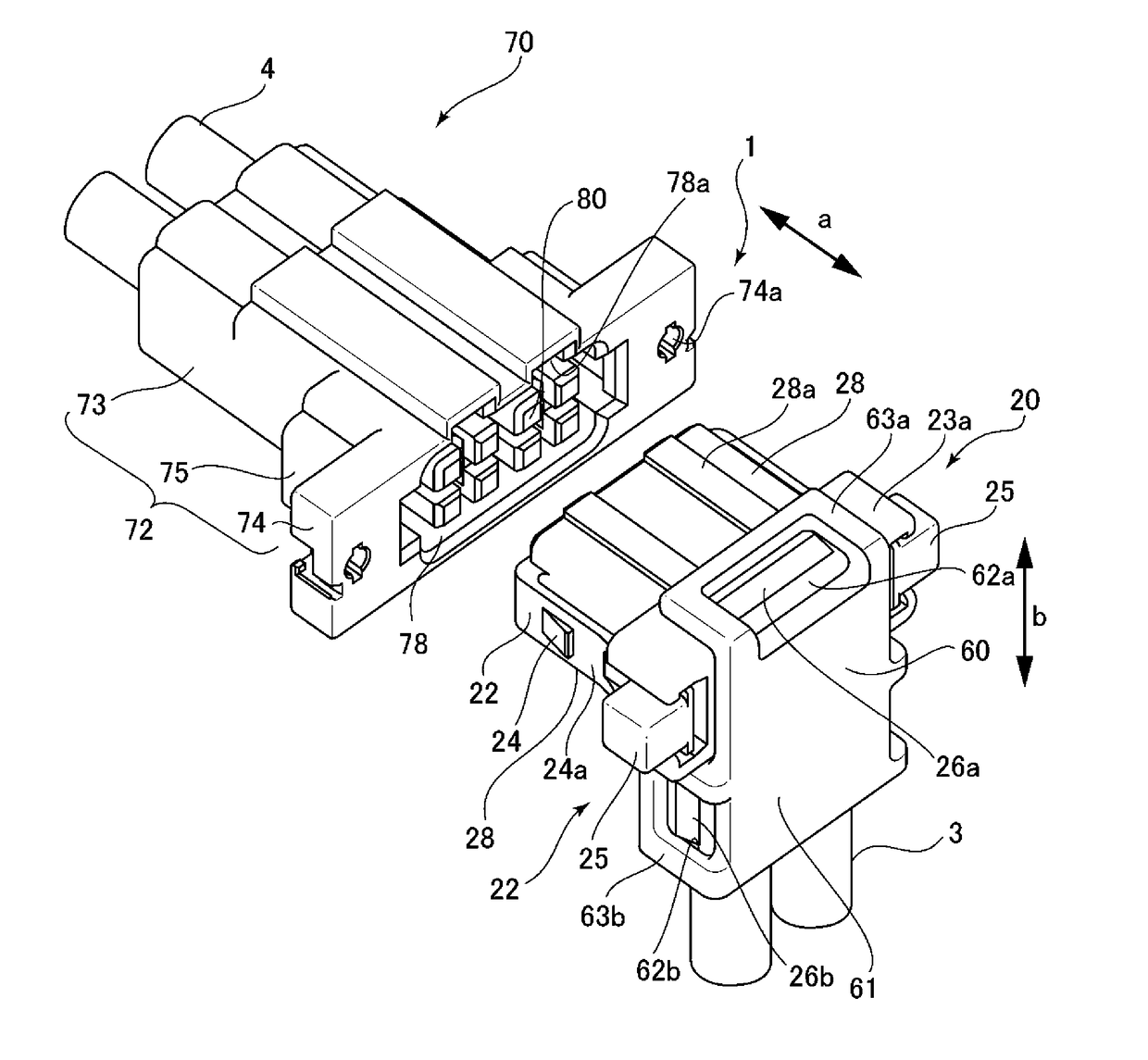
[0042]FIG. 1 is an external perspective view of a power-source connector device according to an embodiment of the invention. A power-source connector device 1 includes a pair of power-source connectors 20 and 70. The power-source connector 20 may be, for example, a plug connector. The power-source connector 70 may be, for example, a socket connector. The plug connector 20 and the socket connector 70 each have a symmetrical shape. The plug connector 20 is insertable into and removable from the socket connector 70 in a direction of arrow “a” in FIG. 1.

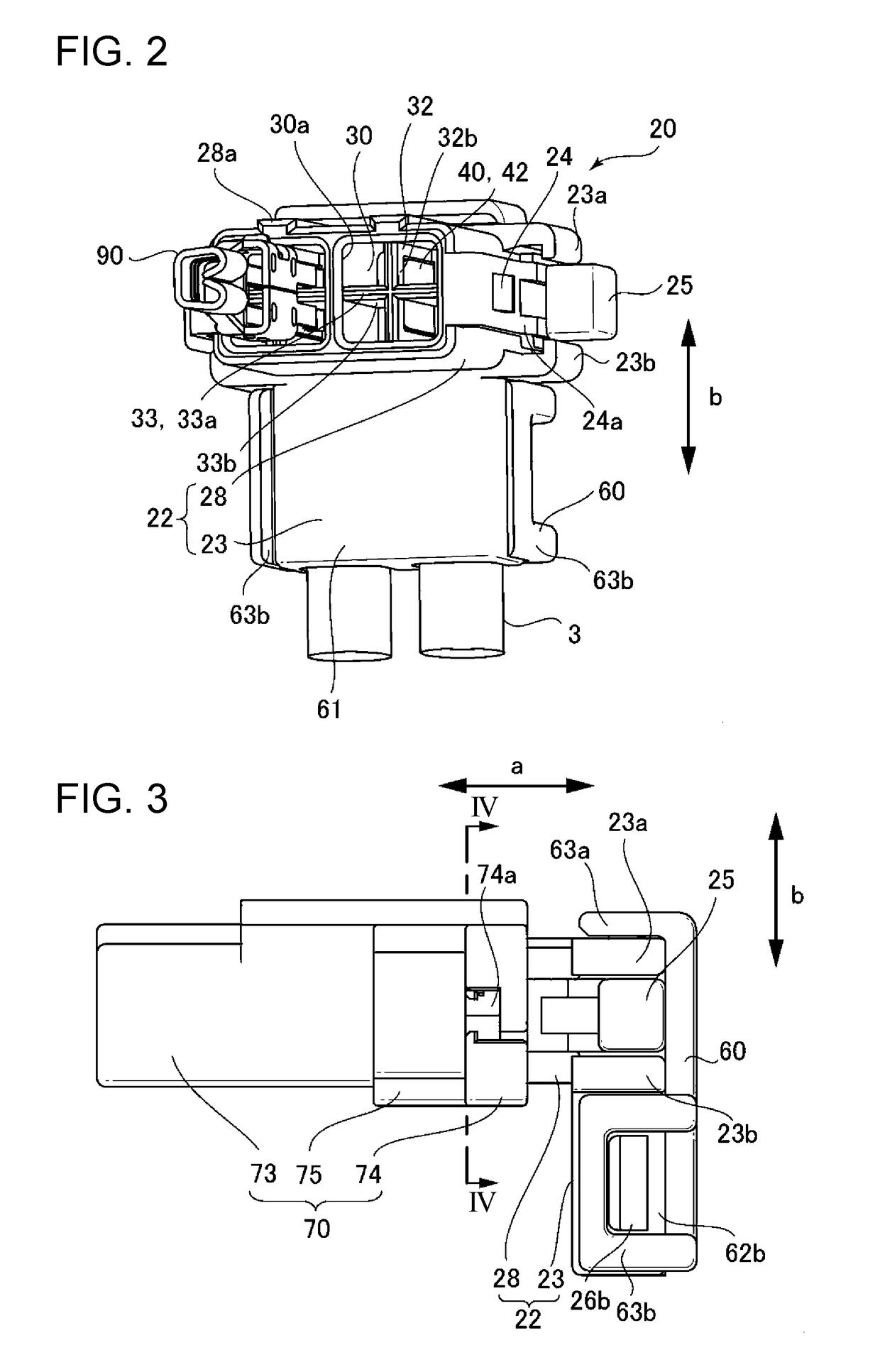
[0043]FIG. 2 is a schematic perspective view of the plug connector 20. For convenience' sake, FIG. 2 illustrates the state where socket terminals (electrically conductive members) 90 of the ...


PUM


Abstract

A power-source connector includes a power-source terminal and a housing that supports the power-source terminal. The housing includes at least two adjoining insertion ports, each partitioned by a partitioning member and through any of which an electrically conductive member is inserted, and a housing space, connected to the insertion ports. The power-source terminal includes a contact portion, disposed in the housing space and being contactable with the electrically conductive member inserted through any of the at least two adjoining insertion ports. The contact portion is disposed so as to extend across the at least two adjoining insertion ports.

Description

BACKGROUND OF THE INVENTION1. Field of the Invention[0001]The present invention relates to a power-source connector including a mechanism, for example, for preventing fingers from touching terminals and to a power-source connector device including the same.2. Description of the Related Art[0002]Japanese Unexamined Patent Application Publication No. 2014-179290 discloses an example of a power-source connector including a mechanism for preventing terminals from being touched. A front surface of the power-source connector has an opening connected to a receiving portion that receives a terminal. A counterpart terminal of a counterpart power-source connector is inserted into the receiving portion through the opening and connected to the terminal disposed in the receiving portion. In the connector disclosed in Japanese Unexamined Patent Application Publication No. 2014-179290, an insulating member is fixed to a tip end of the terminal to prevent a finger inserted by mistake into the recei...

Claims


Application Information

Patent Timeline
IPC IPC(8): H01R13/424H01R13/627H01R13/506
CPCH01R13/424H01R13/627H01R13/506H01R13/4223H01R13/44H01R13/6273H01R13/22
Inventor ONO, SHOZO
Owner HIROSE ELECTRIC GROUP
Why Eureka
Try Eureka