
Autostereoscopic display device

a display device and display panel technology, applied in the field of autostereoscopic display devices, can solve the problems of inability to autostereoscopic viewing effect, rotatable hand held devices, and fixed lenticular arrangement that cannot be used in autostereoscopic viewing, and achieve the effect of preventing banding problems and good performan

Active Publication Date: 2017-10-26
KONINKLJIJKE PHILIPS NV
View PDF0 Cites 31 Cited by
  • Summary
  • Abstract
  • Description
  • Claims
  • Application Information

AI Technical Summary

Benefits of technology

The invention provides design parameters for display panels that solve the problem of "banding" (when a display appears to have lines or borders around it). These design parameters allow for the creation of rotatable multi-view autostereoscopic 3D displays that have good performance. The design space is progressively improved by excluding areas that have poor banding performance.

Problems solved by technology

However, many hand held devices are rotatable between portrait and landscape viewing modes.
Thus, a fixed lenticular arrangement does not allow an autostereoscopic viewing effect in different viewing modes.
Modern LCD and OLED display panels with existing pixel designs are not suited for this application.
One possible disadvantage of this approach is a banding effect, in which the black matrix areas between the sub-pixels are projected to the viewer as a regular pattern.

Method used


Image

  • Autostereoscopic display device
  • Autostereoscopic display device
  • Autostereoscopic display device

Examples


Embodiment Construction

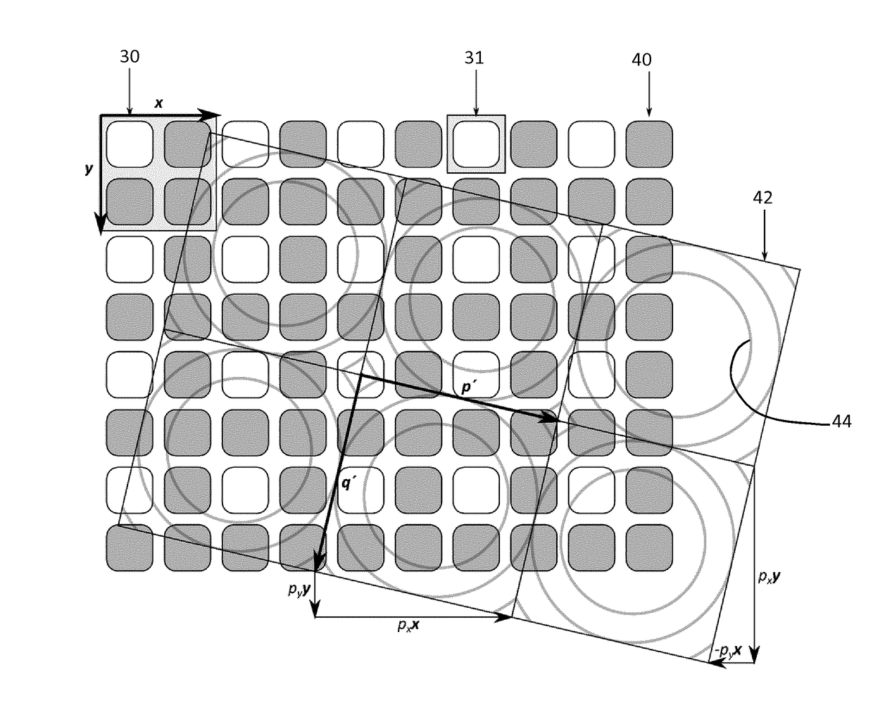
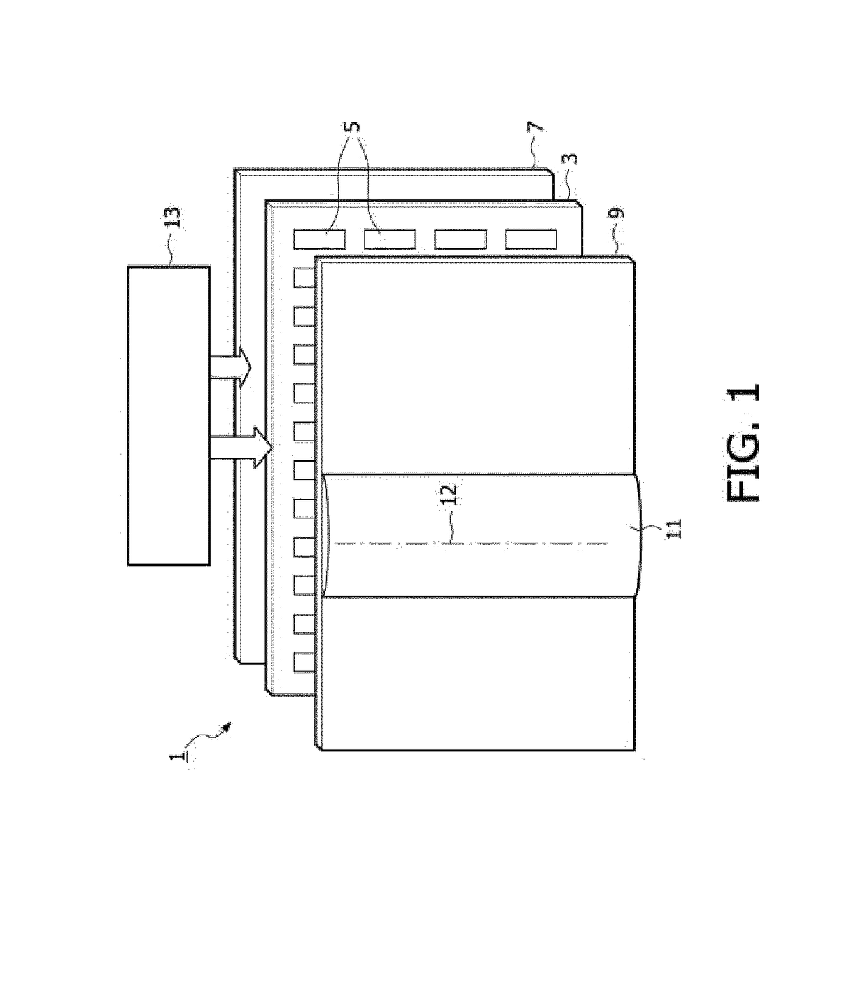
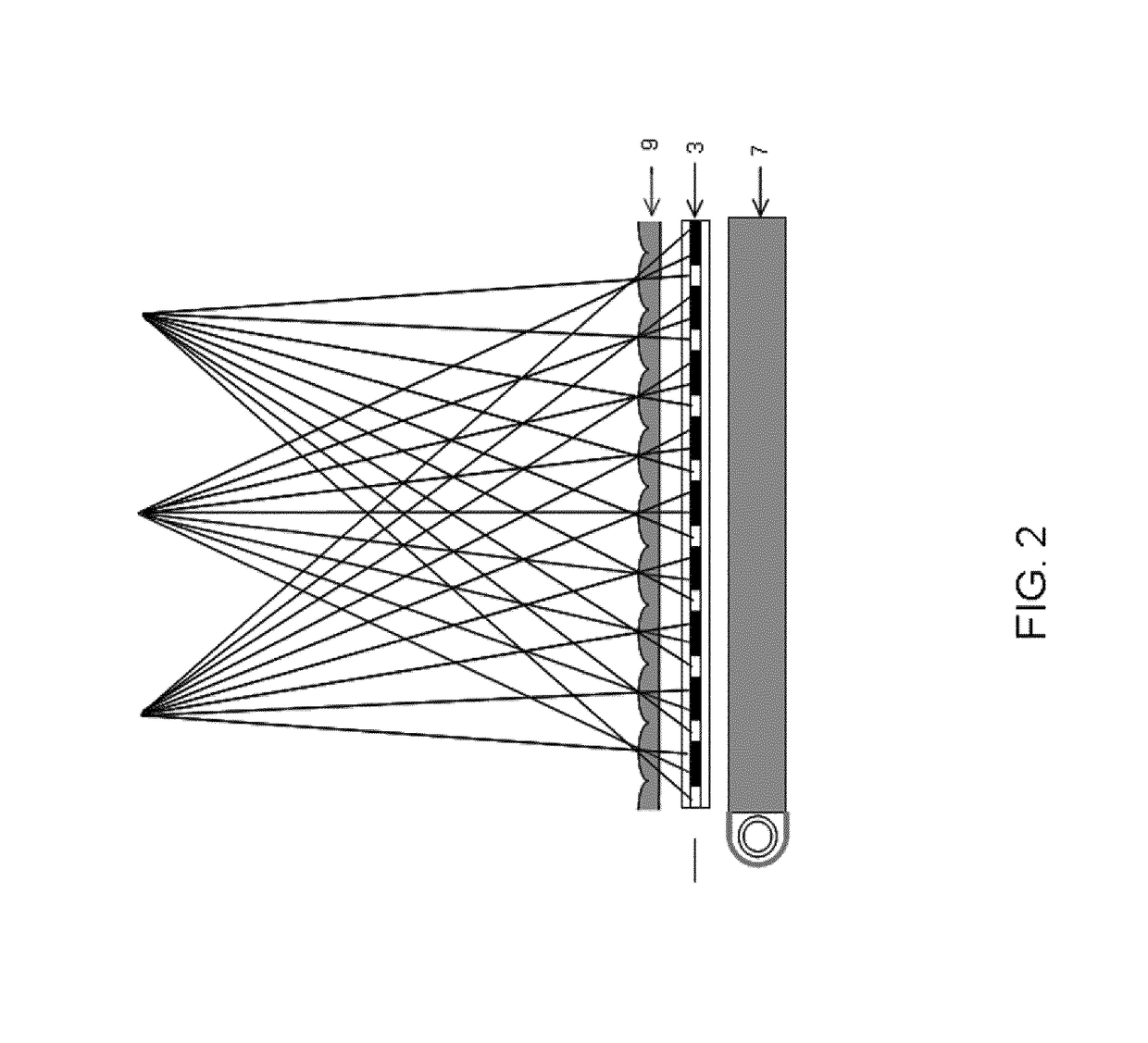
[0070]The invention provides an autostereoscopic display, comprising a pixelated display panel comprising an array of single color pixels or an array of sub-pixels of different colors and a view forming arrangement comprising an array of lens elements. The pixels form a hexagonal grid, and the lenses also repeat in a hexagonal grid. A vector p is defined which relates to a mapping between the pixel grid and the lens grid. Regions in the two dimensional space for this vector p are identified which give good or poor banding performance, and the better banding performance regions are selected.

[0071]The invention is based on an analysis of the effect of the relationship between the pixel grid and the lens grid on the banding performance. The banding analysis can be applied to different pixel and lens designs. Note that the term “pixel grid” is used to indicate the grid of pixels (if each pixel has only one addressable element), or the grid of sub-pixels (if each pixel has multiple indep...


PUM


Abstract

An autostereoscopic display comprises a pixelated display panel comprising an array of single color pixels or an array of sub-pixels of different colors and a view forming arrangement comprising an array of lens elements. The pixels form a hexagonal grid, and the lenses also repeat in a hexagonal grid. A vector p is defined which relates to a mapping between the pixel grid and the lens grid. Regions in the two dimensional space for this vector p are identified which give good or poor banding performance, and the better banding performance regions are selected.

Description

FIELD OF THE INVENTION[0001]This invention relates to an autostereoscopic display device and a driving method for such a display device.BACKGROUND OF THE INVENTION[0002]A known autostereoscopic display device comprises a two-dimensional liquid crystal display panel having a row and column array of display pixels (wherein a “pixel” typically comprises a set of “sub-pixels”, and a “sub-pixel” is the smallest individually addressable, single-color, picture element) acting as an image forming means to produce a display. An array of elongated lenses extending parallel to one another overlies the display pixel array and acts as a view forming means. These are known as “lenticular lenses”. Outputs from the display pixels are projected through these lenticular lenses, whose function is to modify the directions of the outputs.[0003]The pixel comprises the smallest set of sub-pixels which can be addressed to produce all possible colors. For the purposes of this description, a “unit cell” is a...

Claims


Application Information

Patent Timeline
IPC IPC(8): G02B27/22H04N13/04H04N13/305H04N13/307
CPCG02B27/2214H04N13/0404H04N13/0415H04N13/0406H04N13/0422H04N13/324H04N13/307H04N13/305H04N13/317G02B30/27
Inventor VDOVIN, OLEXANDR VALENTYNOVYCHKROON, BARTJOHNSON, MARK THOMASVAN PUTTEN, EIBERT GERJAN
Owner KONINKLJIJKE PHILIPS NV
Learn More