
Analog signal detecting circuit

a detection circuit and analog signal technology, applied in the direction of pulse characteristics measurement, frequency measurement arrangement, instruments, etc., can solve the problems of peak detecting circuit b>2/b> not being able to rectify and smooth the detecting current within the required instantaneous operation time, and not being suitable for earth leakage circuit breaker or circuit breaker, etc., to achieve the effect of reliably detecting even an analog signal, not needing a stabilizing time, and low cost

Active Publication Date: 2017-10-19
LSIS CO LTD
View PDF5 Cites 1 Cited by
  • Summary
  • Abstract
  • Description
  • Claims
  • Application Information

AI Technical Summary

Benefits of technology

The present invention provides an analog signal detecting circuit that can solve problems of requiring a stabilizing time, high manufacturing costs, and difficulty in detecting quickly varying analog signals.

Problems solved by technology

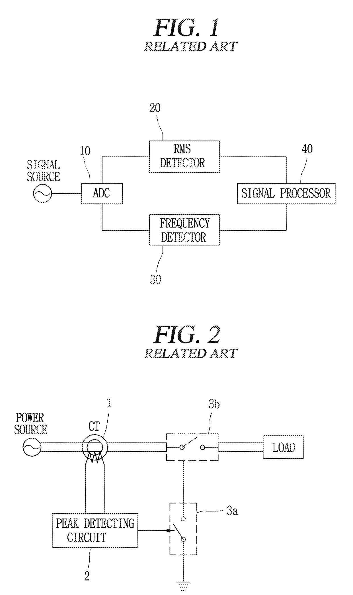
However, the aforementioned example of the related art has a problem in that it is not suitable for the earth leakage circuit breaker or the circuit breaker due to high cost and its magnitude which is not small.
In this case, a problem may occur in that current breaking of a leakage current or a short current can be failed within a required instantaneous operation time due to the stabilizing time.
However, the analog signal detecting circuit according to another example of the related art as shown in FIG. 2 has a problem in that the peak detecting circuit 2 fails to rectify and smooth a detecting current if a rapidly great current as the detecting current flows to the circuit within a short time due to thunderbolt, etc.

Method used


Image

  • Analog signal detecting circuit
  • Analog signal detecting circuit
  • Analog signal detecting circuit

Examples


Embodiment Construction

[0036]Advantages and features of the present invention, and implementation methods thereof will be clarified through following embodiments described with reference to the accompanying drawings FIGS. 3 to 6.

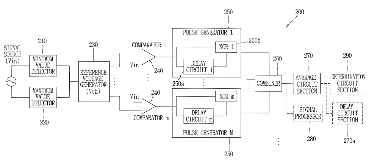
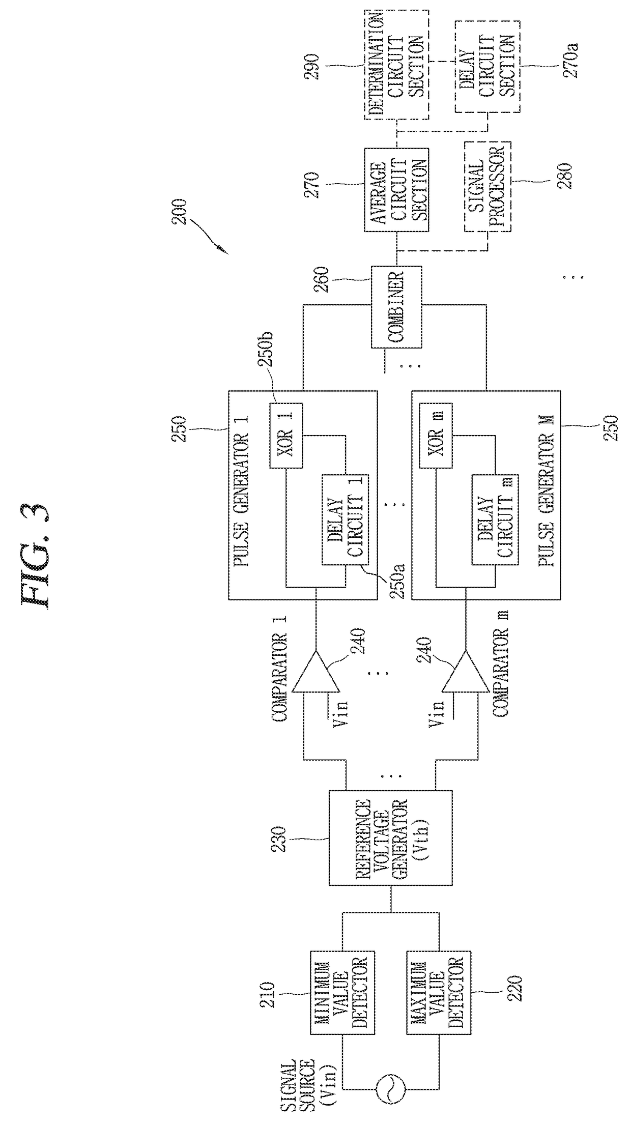
[0037]An analog signal detecting circuit (analog signal detector) 200 according to one preferred embodiment of the present invention comprises a reference voltage generator 230, a plurality of comparators 240, a plurality of pulse generators 250, and a combiner circuit section 260.

[0038]The reference voltage generator 230 is a circuit section that generates a plurality of reference voltages and outputs the reference voltages through a plurality of reference voltage output terminals, wherein the number of the reference voltages is varied depending on a voltage width between a minimum voltage value and a maximum voltage value of an analog signal which is input.

[0039]The analog signal detecting circuit 200 according to one preferred embodiment of the present invention further compris...


PUM


Abstract

The analog signal detecting circuit comprises a reference voltage generator that outputs a plurality of reference voltages, the number of the reference voltages being varied depending on a voltage width between a minimum voltage value and a maximum voltage value of an analog signal; a plurality of comparators that compares a voltage of the analog signal with each of the plurality of reference voltages output from the reference voltage generator; a plurality of pulse generators that outputs a plurality of pulse signals having widths among the plurality of pulse signals varied depending on a frequency of the analog signal; and a combiner circuit section that outputs the pulse signals from the plurality of pulse generators by summing up.

Description

CROSS-REFERENCE TO RELATED APPLICATION[0001]Pursuant to 35 U.S.C. §119(a), this application claims the benefit of earlier filing date and right of priority to Korean Application No. 10-2016-0047193, filed on Apr. 18, 2016, the contents of which are all hereby incorporated by reference herein in its entirety.BACKGROUND OF THE INVENTION1. Field of the Invention[0002]The present invention relates to an analog signal detecting circuit, and more particularly, to an analog signal detecting circuit that can reliably detect an abnormal signal by simultaneously detecting a magnitude and a frequency of an analog signal.2. Description of the Related Art[0003]The present invention relates to an analog signal detecting circuit that can reliably detect an analog signal of a fault current such as a leakage current or a short current for an earth leakage breaker or a circuit breaker. In this analog signal detecting circuit, an example of the related art will be described with reference to FIGS. 1 a...

Claims


Application Information

Patent Timeline
Patent Type & Authority Applications(United States)
IPC IPC(8): G01R19/10G01R19/165H02H3/16
CPCG01R19/10H02H3/16G01R19/16571G01R19/16528G01R31/50G01R19/00G01R19/16566G01R23/06G01R23/15G01R23/10G01R19/16576G01R19/30G01R29/02
Inventor SEON, JONGKUG
Owner LSIS CO LTD
Learn More