Two-channel array for moving target indications

a two-channel array and indication technology, applied in the field of radar antenna systems, can solve problems such as this, but not the cas

Active Publication Date: 2017-07-27
INFORMATION SYST LAB
View PDF2 Cites 2 Cited by
  • Summary
  • Abstract
  • Description
  • Claims
  • Application Information

AI Technical Summary

Benefits of technology

[0008]In accordance with the present invention, a radar antenna system is provided that effectively incorporates a single waveform transmitter which cooperates with two receivers to achieve four degrees of freedom (i.e. four different perspectives) for use in creating a radar indicator. Specifically, with the four degrees of freedom provided by the present invention, the system is able to achieve target detection and high-resolution angle estimation for slow-moving targets in clutter (i.e. endo-clutter targets). Also, it is an important aspect of the present invention that the radar antenna system is compatible for use in either a substantially Synthetic Aperture Radar (SAR) mode, or a substantially Ground Moving Target Indication (GTMI) mode. With this compatibility, the present invention is particularly suitable for use on an Unmanned Aerial Vehicle (UAV) platform.
[0011]As mentioned above, in addition to the single wideband waveform transmitter, the system of the present invention also includes two receiver antennas (i.e. a first receiver antenna and a second receiver antenna). Together, the two receivers establish two receiver spatial degrees of freedom. Within this structure, both the first receiver antenna and the second receiver antenna will simultaneously receive echoes (i.e. return signals) of the transmitted pulses, regardless of their modulation. Further, as a result of the unique switching and phasing on the first transmitted signal path discussed above, it is possible to reorder the received pulses (echoes) at each receiver. Importantly, this reordering separates pulses according to the unique steering direction of the transmitted beam (i.e. φA or φF). Thus, this reordering effectively synthesizes an additional two transmit spatial degrees of freedom. When combined, the two receive spatial degrees-of-freedom, and the two transmit degrees of freedom, provide for a total of four spatial degrees of freedom.

Problems solved by technology

This, however, is not the case with the series of half-power pulses that are sent along the first path.

Method used


Image

  • Two-channel array for moving target indications
  • Two-channel array for moving target indications
  • Two-channel array for moving target indications

Examples


Embodiment Construction

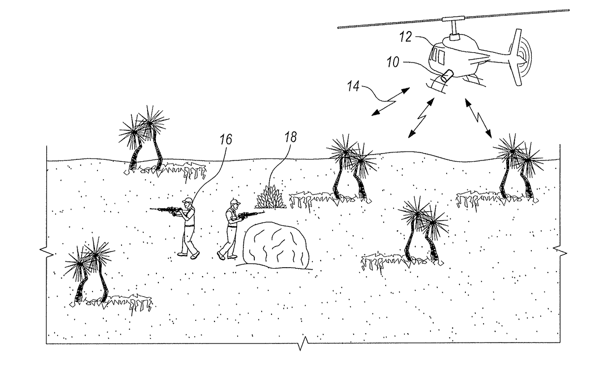
[0020]Referring initially to FIG. 1 a radar antenna system in accordance with the present invention is shown in an operational environment and is designated 10. As shown, the system 10 is mounted on an Unmanned Aerial Vehicle (UAV) 12 to generate a pulsed radar beam 14 that can be used to detect a slow moving target 16 (e.g. troop movements). As envisioned for the system 10, this will be so, even though the target 16 may be partially obscured by ground clutter 18. For purposes of the present invention, the radar beam 14 can be any wideband waveform known in the pertinent art that can be pulsed in a manner as disclosed below. In operation, there will be a pulse interval “τ” between successive pulses of the radar beam 14. For the system 10, τ will preferably be less than about one second.

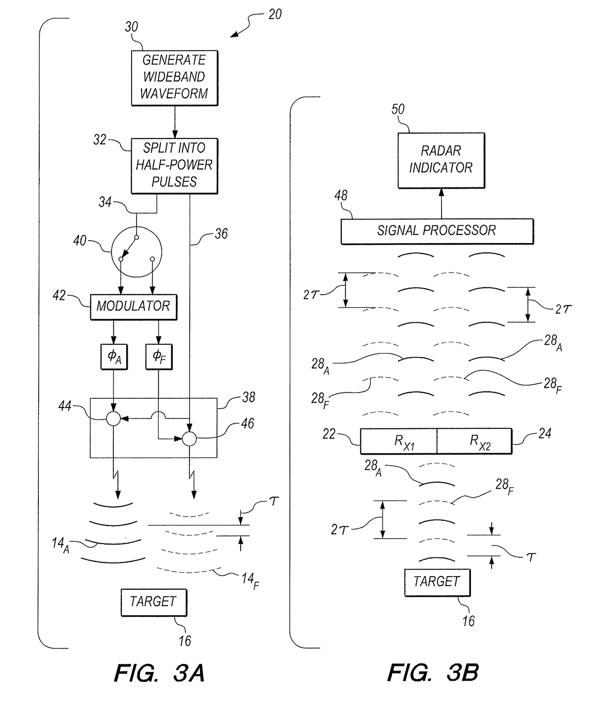
[0021]With reference now to FIG. 2A, it will be seen that the system 10 includes a single transmitter 20 (Tx), but it has two different receive antennas (receivers). These receive antennas are respect...


PUM


Abstract

A radar antenna system includes a single transmitter for creating pulses from a wideband waveform. A splitter divides each pulse into half-power pulses, and sends them along respective paths. On one path, successive half-power pulses are alternately modulated with a phase shift φA or φF. On the other path, the half-power pulses are not modulated. Each modulated half-power pulse is then combined with an un-modulated half-power pulse to transmit pulses of a full aperture beam with either φA or φF. This establishes two degrees of freedom for the system. Two separate receivers then simultaneously receive the pulse echoes and a signal processor uses the consequent four degrees of freedom to create a radar indicator with mitigated clutter and useable azimuth estimation. A coherent processing interval can then be selected for multi-mode operation of the system.

Description

[0001]The U.S. Government has a paid-up license in this invention and the right in limited circumstances to require the patent owner to license others on reasonable terms as provided for by the terms of Contract No. W31P4Q-11-C-0043 awarded by U.S. Army Contracting Command.FIELD OF THE INVENTION[0002]The present invention pertains generally to radar antenna systems. More particularly, the present invention pertains to radar antennas that operate with a single input, to create multiple outputs for enhanced performance of the system with multiple degrees of freedom. The present invention is particularly, but not exclusively, useful as a radar antenna system that incorporates a single wideband waveform transmitter, with two receivers, to achieve four degrees of freedom for use in creating a radar indicator having effective target detection and high-resolution angle estimation for slow-moving targets in clutter (i.e. endo-clutter targets).BACKGROUND OF THE INVENTION[0003]Basically, rada...

Claims


Application Information

Patent Timeline
Patent Type & Authority Applications(United States)
IPC IPC(8): G01S7/41G01S13/02
CPCG01S7/414G01S2013/0254G01S13/0209G01S13/003G01S13/9029G01S2013/0272
Inventor BERGIN, JAMESON S.
Owner INFORMATION SYST LAB
Why Eureka
Try Eureka