
Radiographic imaging device

a radiographic and imaging device technology, applied in the field of radiographic imaging devices, to achieve the effect of easy visual recognition

Active Publication Date: 2017-07-27
SHIMADZU CORP
View PDF1 Cites 1 Cited by
  • Summary
  • Abstract
  • Description
  • Claims
  • Application Information

AI Technical Summary

Benefits of technology

The present patent describes a radiographic imaging device that can improve the visibility of stent images in a live image by preventing the stent image from inverting during playback. This device uses an editing means to create a superimposed frame that always shows the stent image in the same orientation, which prevents the object from appearing upside down. This feature is useful in blood vessel imaging where the position of the blood vessel appears in a superimposed frame and can become difficult to distinguish when the frame is inverted. Overall, this device ensures that the position of the stent image is always visible, making it easier to perform operational procedures.

Problems solved by technology

In this case, for example, in cases where a slight gap is generated between a previously arranged stent and a newly arranged stent, there is a possibility that the gap causes angiostenosis.

Method used


Image

  • Radiographic imaging device
  • Radiographic imaging device
  • Radiographic imaging device

Examples


example 1

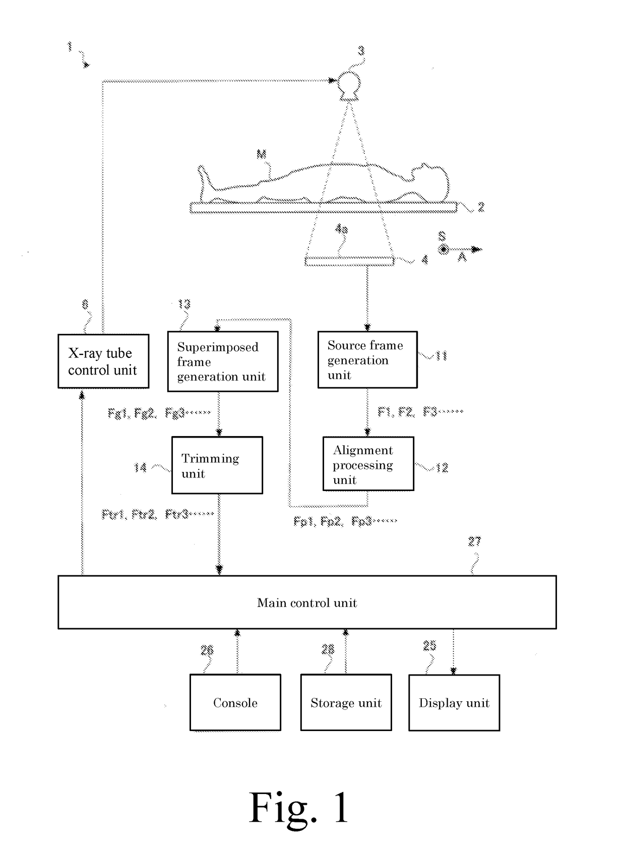
[0085]Hereinafter, exemplary embodiments of the present disclosure will be explained. The X-ray in Examples corresponds to a radiation of the present disclosure. “FPD” is an abbreviation of a flat panel detector. The X-ray equipment 1 of the present disclosure is for treating angiostenosis. To effectively explain features of the present disclosure, it is appropriate to consider the case in which a stent laid in a blood vessel by a previous operation is observed by a moving image. Therefore, in this Example, this case will be described.

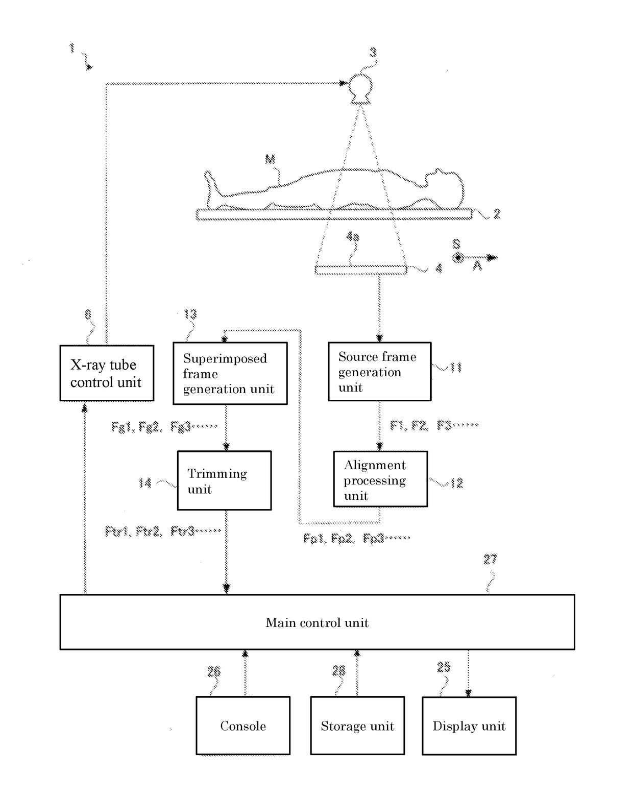
[0086]Initially, a configuration of an X-ray equipment according to Example 1 will be described. The X-ray equipment 1 is provided with a top board 2 on which a subject M is laid as shown in FIG. 1, an X-ray tube 3 arranged on an upper side of the top plate 2 to irradiate an X-ray toward the subject M, and a FPD arranged on a lower side of the top board 2 to detect the X-ray transmitted through the subject M. The FDA 4 is formed into a rectangular shap...


PUM


Abstract

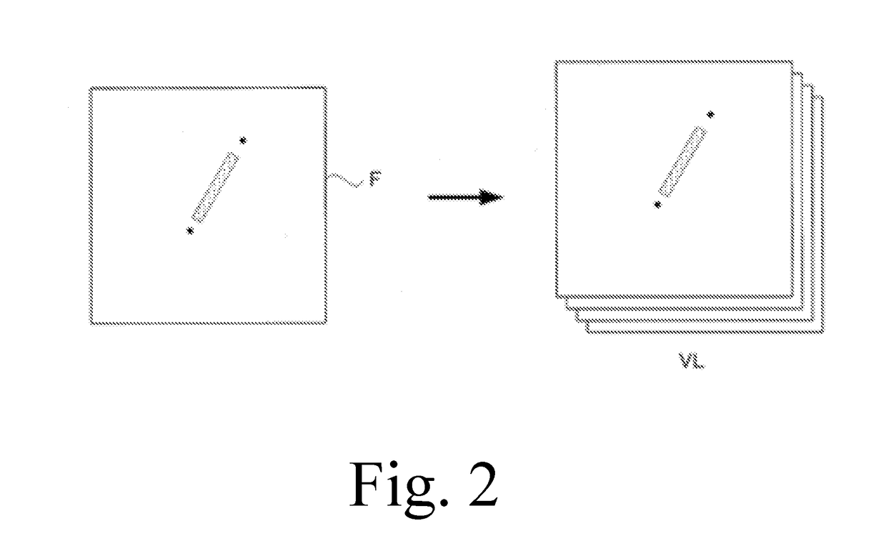
The purpose of the present disclosure is to provide a radiographic imaging device in which visibility is improved by preventing a phenomenon in which a stent image is inverted in an enlarged displayed video of a stent image that appears in a live image. The present disclosure makes it possible to provide a radiographic imaging device in which visibility is improved by preventing a phenomenon in which a stent image is inverted in an enlarged displayed video of a stent image that appears in a live image. Specifically, the present disclosure is provided with a trimming unit that performs editing such that, from among two stent markers indicating the position of a stent image that appears in a superimposed frame generated by superimposing source frames that serve as the source of a live image, a specific stent marker is constantly oriented in the same direction on the frame. As a result of using the trimming unit to edit superimposed frames that are continuously generated, a problem seen in the prior art wherein an object to be displayed within video playback is inverted does not occur.

Description

TECHNICAL FIELD[0001]The present disclosure relates to a radiographic imaging device that acquires an image by irradiating radiation to a subject, and especially to a surgical radiographic imaging device for introducing a stent.TECHNICAL BACKGROUND[0002]In a coronary intervention (PCI) which is a treatment to be carried out for myocardial infraction or angina pectoris, a treatment is carried out such that a catheter equipped with a guide wire therein is inserted from a base of a thigh, etc., into a blood vessel so that the catheter is reached the coronary artery of the heart via the blood vessel. As the device for the coronary intervention treatment, a stent is used. This stent is a medical device made of metal, such as a stainless-steel, and is used to improve treatment effects of a catheter treatment by staying at a stenosis part of a coronary artery expanded using a balloon and holding the blood vessel from the inner cavity. In this case, for example, in cases where a slight gap ...

Claims


Application Information

Patent Timeline
Patent Type & Authority Applications(United States)
IPC IPC(8): A61B6/00
CPCA61B6/461A61B6/5241A61B6/467
Inventor TSUTSUI, KAZUHIKOSATOU, SHOUTAGOTOH, KEIICHIYOSHIDA, TAKANORI
Owner SHIMADZU CORP
Learn More