
System and method for generating and implementing an end-of-row turn path

a technology of end-of-row turn and path, applied in the direction of vehicle position/course/altitude control, process and machine control, instruments, etc., can solve the problem that the operator may not follow the most efficient path through the end-of-row turn, large corrections in heading and alignment, and/or overlap with another swath,

Active Publication Date: 2017-07-20
AUTONOMOUS SOLUTIONS +1
View PDF4 Cites 28 Cited by
  • Summary
  • Abstract
  • Description
  • Claims
  • Application Information

AI Technical Summary

Benefits of technology

The patent describes a method for generating a non-continuous curvature end-of-row turn path for an agricultural vehicle. The turn path includes a plurality of initial segments that are curved or straight, and at least one continuity segment between each initial segment. The continuity segment is a clothoid segment, which is a type of smooth curve. The initial segments and continuity segments combine to form a continuous curvature end-of-row turn path. The method can be implemented by an agricultural vehicle control system, which generates the continuous rate of curvature end-of-row turn path based on information from a navigation system and the vehicle's steering system. The non-continuous curvature end-of-row turn path can be displayed on a screen for the driver's reference. The technical effect of this patent is to provide a more efficient and smooth turning path for agricultural vehicles, which can improve operational efficiency and safety.

Problems solved by technology

The operator may not follow the most efficient path through the end-of-row turn.
Small errors in heading or path through the end-of-row turn can lead to large corrections in heading and alignment while initiating automatic guidance at the beginning of a subsequent swath.
Additionally, if the implement is not aligned with the subsequent swath at the time the implement is lowered or turned on, the implement may miss a portion of the subsequent swath, creating a skip, and / or overlap with another swath.
Skips (e.g., missed sections of a swath) may result in weeds growing, time lost due to backing up and repositioning the vehicle, and / or time lost to filling in by hand.
These errors and corrections may result in significantly reduced efficiency of agricultural operations.

Method used


Image

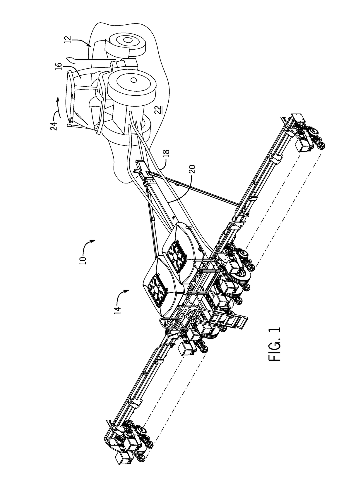
  • System and method for generating and implementing an end-of-row turn path
  • System and method for generating and implementing an end-of-row turn path
  • System and method for generating and implementing an end-of-row turn path

Examples


Embodiment Construction

[0020]One or more specific embodiments of the present disclosure will be described below. In an effort to provide a concise description of these embodiments, all features of an actual implementation may not be described in the specification. It should be appreciated that in the development of any such actual implementation, as in any engineering or design project, numerous implementation-specific decisions must be made to achieve the developers' specific goals, such as compliance with system-related and business-related constraints, which may vary from one implementation to another. Moreover, it should be appreciated that such a development effort might be complex and time consuming, but would nevertheless be a routine undertaking of design, fabrication, and manufacture for those of ordinary skill having the benefit of this disclosure.

[0021]When introducing elements of various embodiments of the present disclosure, the articles “a,”“an,”“the,” and “said” are intended to mean that th...


PUM


Abstract

A method includes generating a non-continuous curvature end-of-row turn path for an agricultural vehicle, wherein the non-continuous curvature end-of-row turn path includes a plurality of initial segments that are curved or straight, adding at least one continuity segment between each of the initial segments, wherein the at least one continuity segment is a clothoid segment, and the initial segments and the at least one continuity segment combine to form a continuous curvature end-of-row turn path, and implementing the continuous end-of-row turn path, displaying the continuous end-of-row turn path, or both.

Description

BACKGROUND[0001]This disclosure relates generally to agricultural vehicle guidance systems, and more particularly to generating and implementing end-of-row turn paths for an agricultural vehicle.[0002]Agricultural vehicles (e.g., tractors, harvesters, etc.) are commonly used in a variety of agricultural tasks (e.g., to tow planters or seeders for planting seeds, to tow spraying implements for applying fertilizer, for harvesting agricultural product, etc.). Traditionally, agricultural vehicles have been manually operated by the operator. That is, the steering and speed of an agricultural vehicle have been controlled by an operator driving the vehicle. Recent developments integrating GPS-based navigation systems into agricultural vehicle control systems have enabled automatic or semi-automatic steering modes. For example, some agricultural vehicles may include a control system configured to automatically direct the vehicle to follow a path between, over, or adjacent to rows in a field...

Claims


Application Information

Patent Timeline
IPC IPC(8): A01B69/04A01B79/00B60W10/04G01C21/10B60W30/10B60W10/20
CPCA01B69/008B60W30/10B60W10/20B60W2300/15G01C21/10A01B79/005B60W10/04A01B69/004G05D1/0212G05D1/0217G05D1/0219G05D1/0223
Inventor BUNDERSON, NATHAN ERICMORWOOD, DANIEL JOHNRAY, BRIAN ROBERTDIX, PETER JOHNMCCARTHY, BRENDAN PAULTURPIN, BRET TODDMCCLELLAND, BRETT
Owner AUTONOMOUS SOLUTIONS
Learn More