Ultra broad band continuously tunable electron beam pulser

a pulser and ultra-wideband technology, applied in the direction of electrical equipment, electric discharge tubes, basic electric elements, etc., can solve the problems of high repetition rate, 1 ghz, and simply not being able to laser-excited electron beams

Active Publication Date: 2017-06-08
EUCLID TECHLABS LLC +1
View PDF0 Cites 6 Cited by
  • Summary
  • Abstract
  • Description
  • Claims
  • Application Information

AI Technical Summary

Benefits of technology

[0030]An additional feature of the TWTS is that the electric field of the transverse electromagnetic mode is always perpendicular to the beam propagation direction, so that the electric field of the TWTS does not contribute to the longitudinal distortion of the beam, thereby helping to preserve the energy coherence of the beam, and making it possible for embodiments to produce electron pulse lengths as short as 100 fs or less at pulse repetition rates of greater than 10 GHz.
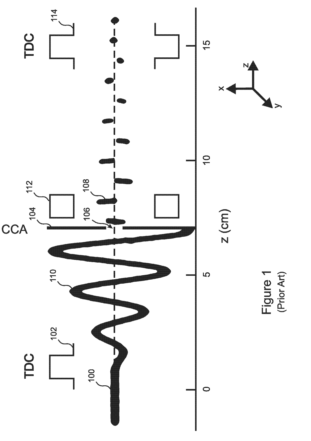
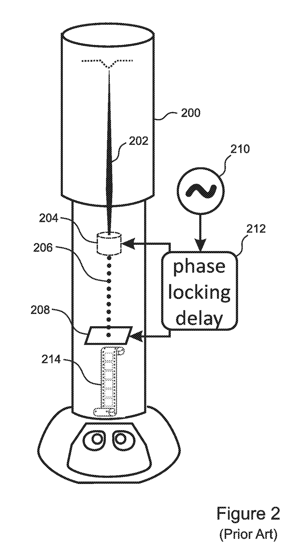
[0032]Devices that incorporate the disclosed TWTS-EMMP approach can provide ultra-wideband, continuous pulse rate variability in addition to all of the same benefits that are described above and in Ultramicroscopy 161 (2016) 130-136 with respect to TDC-EMMP devices.

Problems solved by technology

However, high repetition rates, defined herein as being repetition rates of at least 1 GHz or higher, are simply not available for laser-excited electron beams, because modern lasers are only capable of repetition rates on the order of 100 MHz or less (0.1 GHz or less).
However, these approaches, which typically employ just one single-cell deflecting cavity, are generally limited to pulse lengths of 1 picosecond (“ps”) at best and repetition rates of 1 GHz or less, which cannot be changed or tuned.
Furthermore, these approaches are only applicable for generating low energy electron beams having energies of less than 100 kilo-electron Volts (“keV”).
Perhaps even more importantly, these approaches typically result in very extensive electron beam quality deterioration in both the transverse direction (beam diameter and divergence) and longitudinal direction (temporal coherence).
Nevertheless, while the TDC-EMMP has many advantages, the use of a TDC to impose the spatial oscillation onto the beam imposes some inherent limitations.

Method used


Image

  • Ultra broad band continuously tunable electron beam pulser
  • Ultra broad band continuously tunable electron beam pulser
  • Ultra broad band continuously tunable electron beam pulser

Examples


Embodiment Construction

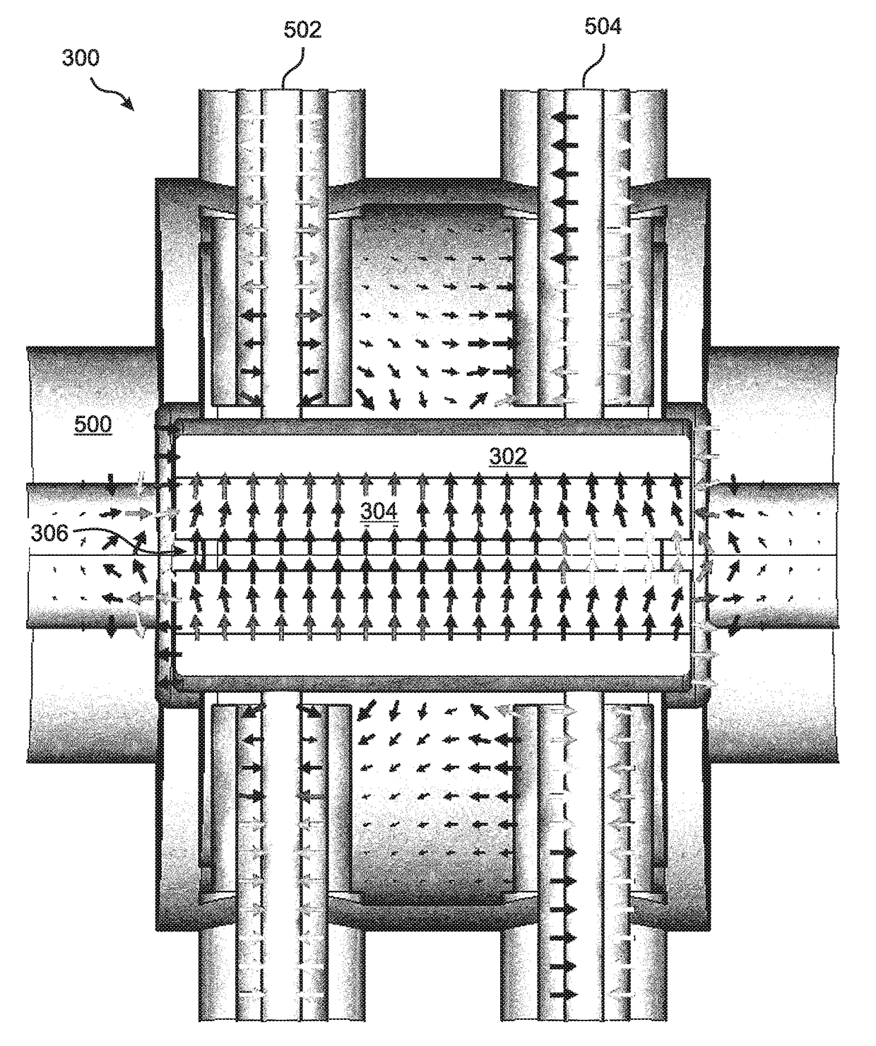
[0061]A novel EMMP, referred to herein as a TWTS-EMPP is disclosed that is able to produce a pulsed electron beam which is continuously tunable over a wide range of pulse widths and pulsing frequencies. As noted above, the previously introduced TDC-EMMP is limited to only certain discrete pulsing frequencies (i.e. pulse repetition rates) due to the use of a resonant cavity (TDC) as the mechanism for imposing spatial oscillations onto an electron beam. The present invention replaces this oscillation-imposing TDC with a novel Travelling Wave Transmission Stripline (“TWTS”) modulator. In embodiments, the rate of electron pulses produced by the disclosed TWTS-EMMP system can be continuously adjusted between 100 MHz and 20 GHz. In still other embodiments, the TWTS-EMMP system can be continuously adjusted between 100 MHz and 50 GHz.

[0062]With reference to FIG. 3, the TWTS 300 in its most general form includes an outer conductive shell 302 filled with a dielectric 304, which is penetrated ...


PUM


Abstract

An ElectroMagnetic-Mechanical Pulser (“EMMP”) generates electron pulses at a continuously tunable rate between 100 MHz and 20-50 GHz, with energies up to 0.5 MeV, duty cycles up to 20%, and pulse widths between 100 fs and 10 ps. A dielectric-filled Traveling Wave Transmission Stripline (“TWTS”) that is terminated by an impedance-matching load such as a 50 ohm load imposes a transverse modulation on a continuous electron beam. The dielectric is configured such that the phase velocity of RF propagated through the TWTS matches a desired electron energy, which can be between 100 and 500 keV, thereby transferring electromagnetic energy to the electrons. The beam is then chopped into pulses by an adjustable aperture. Pulse dispersion arising from the modulation is minimized by a suppressing section that includes a mirror demodulating TWTS, so that the spatial and temporal coherence of the pulses is substantially identical to the input beam.

Description

RELATED APPLICATIONS[0001]This application claims the benefit of U.S. Provisional Application No. 62 / 262,850, filed Dec. 3, 2015. This application is related to U.S. patent application Ser. No. 15 / 091,639, filed Apr. 6, 2016. Both of these applications are herein incorporated by reference in their entirety for all purposes.FIELD OF THE INVENTION[0002]The invention relates to apparatus and methods for generating pulsed electron beams, and more particularly, to apparatus and methods for generating and controlling low and medium energy pulsed electron beams at very high rates.BACKGROUND OF THE INVENTION[0003]Generation and precise control of low and medium energy pulsed electron beams is required for many industrial, medical, and research applications, including scanning electron microscopy (SEM), transmission electron microscopy (TEM), and horizontal / vertical accelerator-based beamlines (HAB / VAB), as well as relevant experimental analytical methods that use electron beams in SEM or TE...

Claims


Application Information

Patent Timeline
Patent Type & Authority Applications(United States)
IPC IPC(8): H01J37/065H01J37/04
CPCH01J37/065H01J2237/065H01J37/045
Inventor JING, CHUNGUANGQIU, JIAQIBARYSHEV, SERGEY V.LAU, JUNE W.ZHU, YIMEI
Owner EUCLID TECHLABS LLC
Why Eureka
Try Eureka