
Dynamic text scroll control in a user interface

a scroll control and user interface technology, applied in the field of user interface functions, can solve the problems of text or figure details that are difficult to visualiz

Active Publication Date: 2017-05-25
IBM CORP
View PDF3 Cites 3 Cited by
  • Summary
  • Abstract
  • Description
  • Claims
  • Application Information

AI Technical Summary

Benefits of technology

The present invention provides a method for dynamic text scroll control in a user interface. This method allows for the creation of overlapping text stacks and the use of a scroll mechanism to display these overlapping elements. The technical effect of this invention is improved user experience and ease of use for scanning and navigating through numerous display elements.

Problems solved by technology

Alternatively, a zooming feature may be useful when the viewing information is significantly smaller than the screen size, making either text or figure details difficult to visualize.

Method used


Image

  • Dynamic text scroll control in a user interface
  • Dynamic text scroll control in a user interface
  • Dynamic text scroll control in a user interface

Examples


embodiment 410

[0045]Embodiment 410 represents time at T=0, when display 412 and order relation 414 are initially empty. Display 412 and order relation 414 are empty as display scroll program 124 has not received information to display (per step 210).

embodiment 420

[0046]Embodiment 420, represents time at T=1, where display scroll program 124 displays, on display area 422, text areas 1, 4, 6, while text areas 2, 3, 5, 7, and 8 are hidden. Display scroll program 124 groups the 8 different text areas into 3 separate groupings. Order relation 424 is updated to represent the corresponding displayed text groupings. The left column of order relation 424, represents the displayed text areas, while a corresponding right column represents hidden text areas.

[0047]Embodiment 430, represents time at T=2, where display scroll program 124 establishes new text area groupings as display area 432 is zoomed out. Display scroll program 124 displays, on display area 432, text areas 1 and 5 while text areas 2, 3, 4, 6, 7, and 8 are hidden. Therefore, the order relation is updated and ordered based on the precedence. For illustration, order relation pair 1-2, 1-3, 4-5, 6-7, and 6-8, are carried over from embodiment 420 at time T=1. It is noted that the order relati...

embodiment 450

[0050]Embodiment 450 represents time at time T=4, when the user actively zooms-in, thereby re-creating the precedence between text areas at time T=2. However, due to the pairing conflict at time T=3, display area 452 displays text area 7 and hides text area 6 and 8 (as compared to display area 422 which displayed text area 6 and hid text areas 7 and 8).

[0051]FIGS. 4B-4D, illustrate how an order relation is used to recall history as text areas are manipulated. For example, operations such as zoom-in, zoom-out, and text scroll often create new precedence between text areas. As noted in FIG. 4A, the order relation memorizes only the most recent precedence between two text areas. FIG. 4B illustrates an example of the change where H0 is the initial order relation and H1, and H2 represent an order relation at certain points later in time. (Reference to FIG. 4A: H0 represents embodiment 410, at time T=0, H1 represents embodiment 430 at time T=2 and H2 represents embodiment 440 at time T=3....


PUM


Abstract

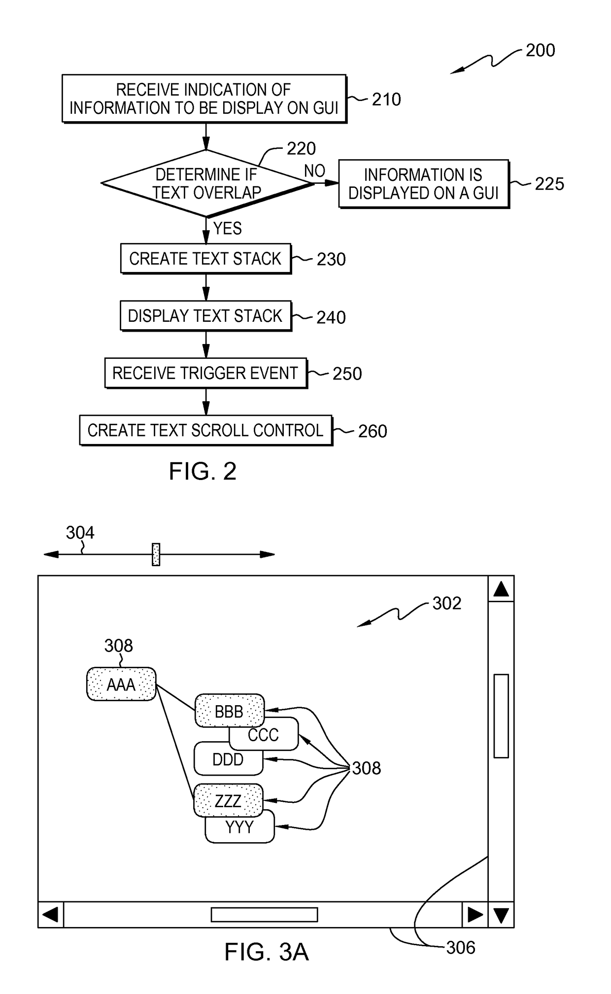
Embodiments of the present invention provide a method and system for displaying overlapping text elements on a graphical user interface. Initially, it is determined, whether a first display elements overlaps a second display element. If, the first display elements overlaps the second display element, then a text stack is created of all overlapping display elements. Only an identified display element is displayed on the text stack. Finally, a scroll mechanism is provided which allows a user to scroll through and display the first and second set of display elements which overlap.

Description

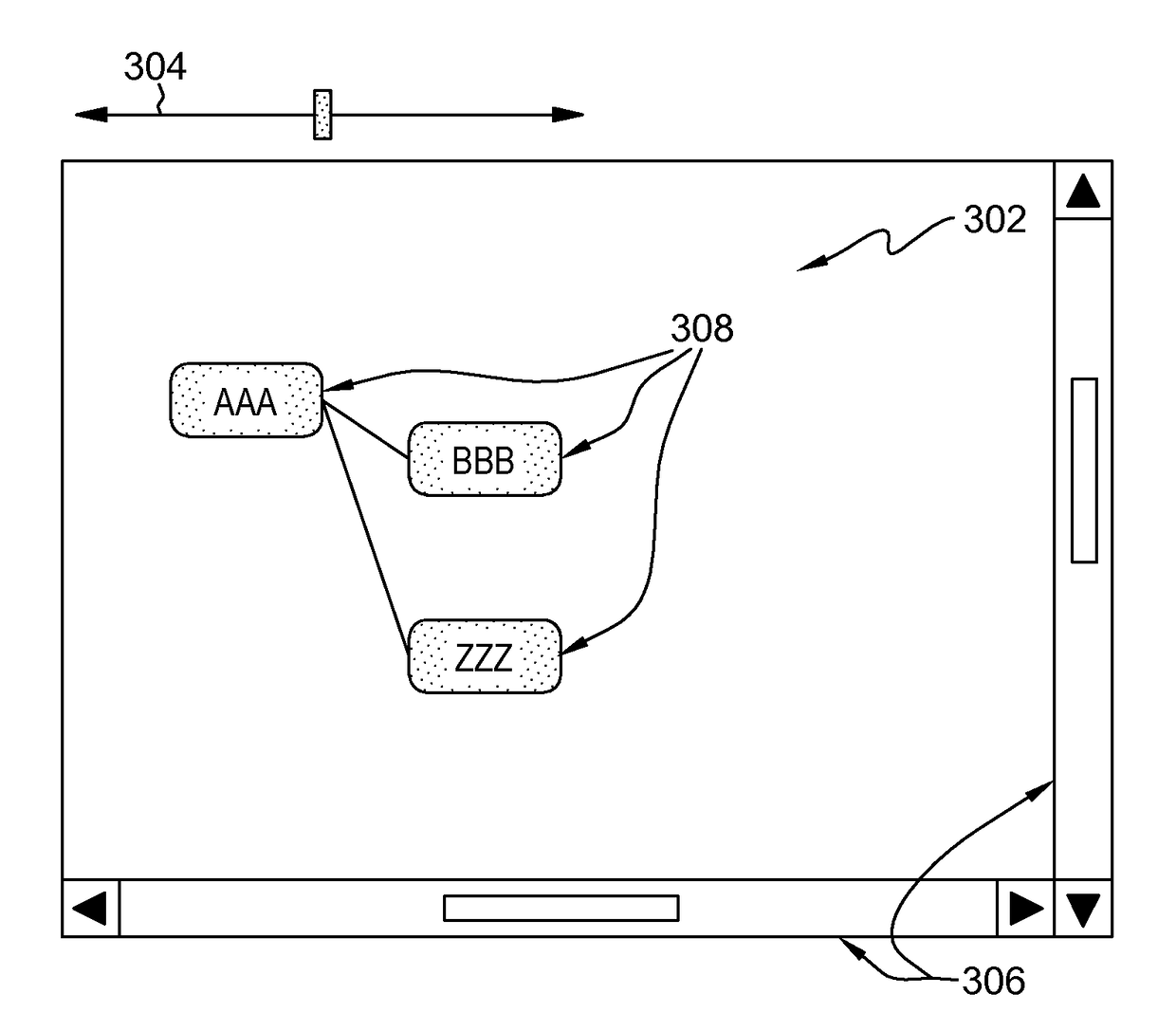
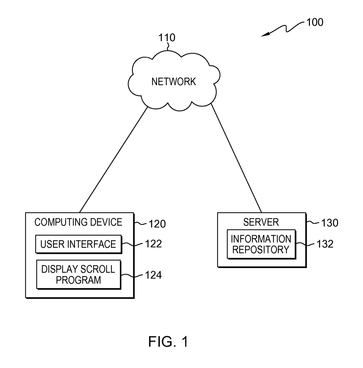
BACKGROUND OF THE INVENTION[0001]The present invention relates generally to the field of user interface functions, and more particularly to displaying overlapping text elements using a text scroll control bar.[0002]Electronic devices such as cellular phones, smart phones, mobile phones, Wi-Fi phones, laptop computers, tablet computers, netbooks, handheld computers, personal organizers, e-reading devices, gaming devices and the like, may provide a graphical user interface that allows users to easily interact with the various functionalities of the electronic device. Many graphical user interfaces provide a zoom feature, which allows a user to increase or decrease the size of an object on the display. A zooming feature may be useful when the viewing information is larger than the screen size. Alternatively, a zooming feature may be useful when the viewing information is significantly smaller than the screen size, making either text or figure details difficult to visualize.SUMMARY[0003...

Claims


Application Information

Patent Timeline
Patent Type & Authority Applications(United States)
IPC IPC(8): G06F3/0485G06F3/0481
CPCG06F3/0481G06F3/0485G06F9/451
Inventor FUKUDA, SUSUMUHORIUCHI, YOSHIOKINOSHITA, SATOKOMITSUI, KINICHI
Owner IBM CORP
Learn More