
Fluid conditioning systems having caps with filter cartridge sealing and removal devices and/or locking devices

a technology of filter cartridges and sealing devices, applied in the direction of membranes, filtration separation, separation processes, etc., can solve the problems of difficult sealing and removal of filter cartridges from the interior of the container, and achieve the effect of improving locking devices

Active Publication Date: 2017-05-18
UNGER MARKETING INT
View PDF1 Cites 12 Cited by
  • Summary
  • Abstract
  • Description
  • Claims
  • Application Information

AI Technical Summary

Benefits of technology

The patent describes a fluid conditioning system that uses a reverse osmosis unit with a cap that can be easily removed to install and remove a filter cartridge. The design of the cap and filter cartridge minimizes friction during installation and removal. Additionally, the cap can also have a locking device that is easily unlocked by simply unscrewing the cap. This simplifies the use of the fluid conditioning system. The technical effect of this invention is to provide a convenient and easy-to-use fluid conditioning system.

Problems solved by technology

It has been determined by the present disclosure that the sealing and removal of filter cartridges from the interior of the container can be made difficult by the force of the cartridge seals and the inner wall of the container.
Additionally, it has been determined by the present disclosure that the caps of the prior art have complicated locking devices that require, for example, two hand operation and / or multiple locking and unlocking steps.

Method used


Image

  • Fluid conditioning systems having caps with filter cartridge sealing and removal devices and/or locking devices
  • Fluid conditioning systems having caps with filter cartridge sealing and removal devices and/or locking devices
  • Fluid conditioning systems having caps with filter cartridge sealing and removal devices and/or locking devices

Examples


Embodiment Construction

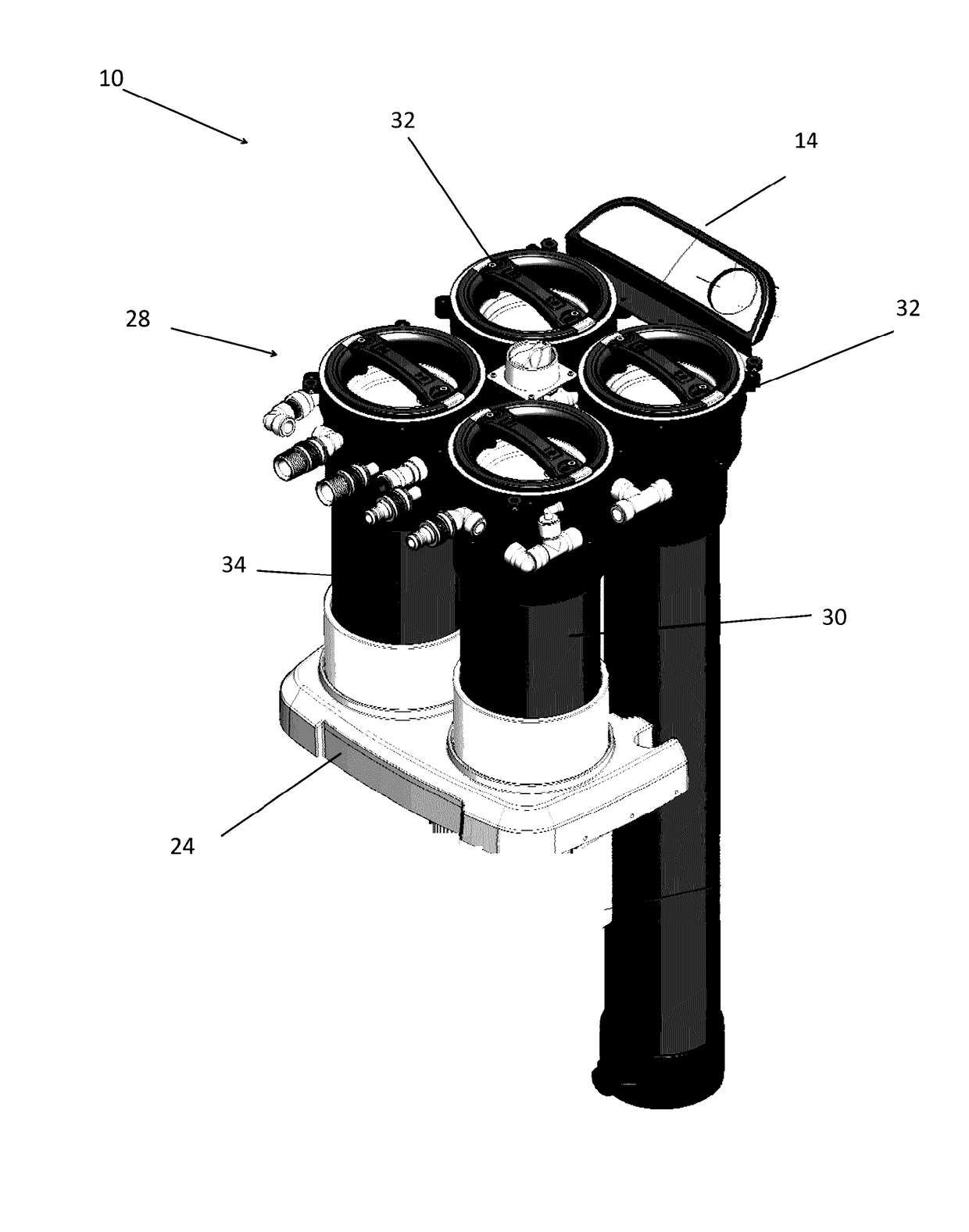
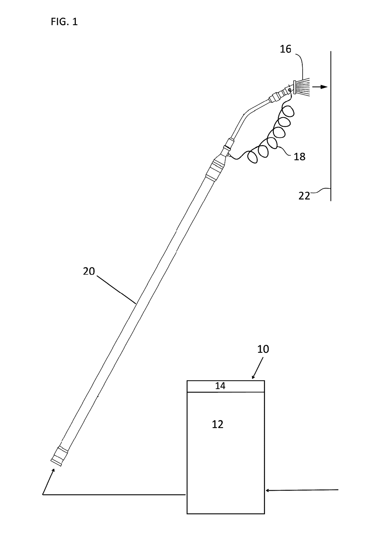
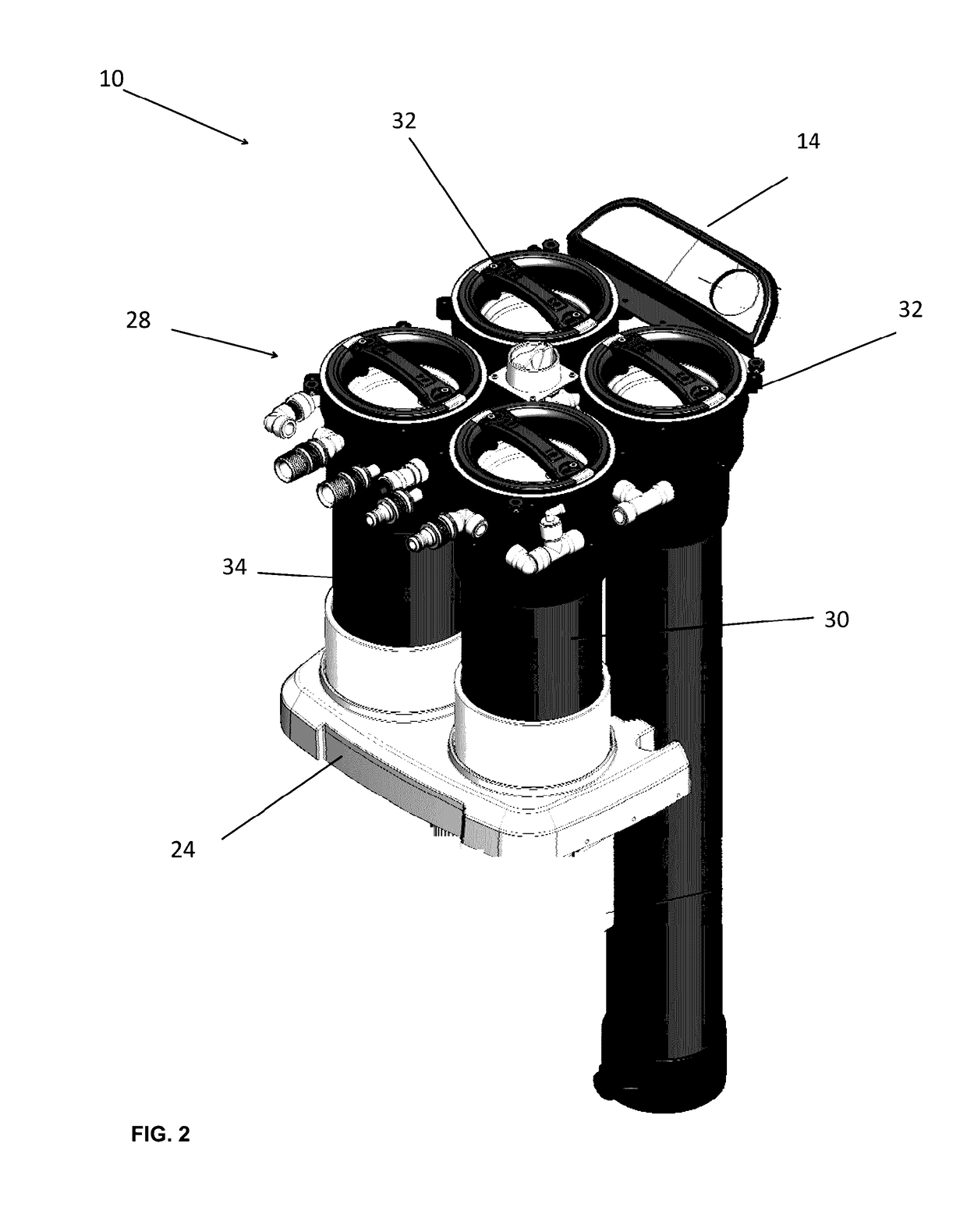
[0055]Referring to the drawings and in particular to FIGS. 1 and 2, an exemplary embodiment of a fluid conditioning system according to the present disclosure is shown and is referred to as reference numeral 10. System 10 includes a fluid conditioner 12 in communication with a controller 14, which is configured to operate system 10.

[0056]Conditioner 12 is shown by way of example in fluid communication with a fluid-fed cleaning brush 16 via one or more tubes 18 and is secured to an extension pole 20 so that the conditioned fluid can clean a desired surface 22. Of course, other uses of system 10 are contemplated by the present disclosure.

[0057]As discussed above, “conditioned fluid” means fluid that has been filtered, deionized, demineralized, softened, exposed any other fluid treatment process—including the addition of one or more additives or components, and any combinations thereof. Accordingly, conditioner 12 can include a particle filter, a chlorine filter (i.e., activated carbon...


PUM

PropertyMeasurementUnit
unthreading forcesaaaaaaaaaa
threading forcesaaaaaaaaaa
pressureaaaaaaaaaa

Abstract

A fluid conditioning unit is provided that includes a housing, a cap, a cartridge device, and a filter cartridge. The cap is threadably secured to and unsecured from the housing by rotation about an axis of the housing. The cap forms a removable seal with the housing when secured thereto. The cartridge device is secured to the cap in a manner that restricts movement of the cartridge device with respect to the cap along the axis but allows rotation of the cartridge device with respect to the cap about the axis. The filter cartridge is removably secured to the cartridge device and is disposed in the housing along the axis.

Description

CROSS REFERENCE TO RELATED APPLICATIONS[0001]This application claims the benefit of U.S. Provisional Application No. 62 / 254,448 filed on Nov. 12, 2015, claims the benefit of U.S. Provisional Application No. 62 / 342,403 filed on May 27, 2016, claims the benefit of U.S. Provisional Application No. 62 / 342,373 filed on May 27, 2016, and claims the benefit of U.S. Provisional Application No. 62 / 342,380 filed on May 27, 2016, the entire contents of which are incorporated by reference herein.BACKGROUND[0002]1. Field of the Disclosure[0003]The present disclosure is related to fluid conditioning systems. More particularly, the present disclosure is related to caps for such fluid conditioning systems, where the caps include filter cartridge sealing and removal devices and / or locking devices.[0004]2. Description of Related Art[0005]Fluid conditioners that treat an incoming fluid, such as tap water, are known. As used herein, the term “conditioned fluid” shall mean a fluid that has been filtered...

Claims


Application Information

Patent Timeline
Patent Type & Authority Applications(United States)
IPC IPC(8): B01D61/02C02F1/44
CPCB01D61/025C02F1/441B01D2313/02B01D2313/04B01D2313/125C02F2201/006B01D2313/21B01D2313/24B01D2313/44C02F2201/004B01D2313/20B01D61/08Y02W10/37B01D35/1435B01D2201/4076B01D2201/301B01D2201/347B01D15/361C02F1/001C02F1/283C02F1/42B01D2313/206B01D2313/041B01D61/029B01D2311/246B01D61/04B01D61/12B01D2311/14B01D2311/2623B01D2311/2649B01D2317/04C02F1/008C02F2201/008C02F2209/003C02F2209/008C02F2209/03C02F2209/10C02F2307/06C02F5/00
Inventor HUDA, STEPHENHIRSCH, KAIBUCKLEY, JAMES M.
Owner UNGER MARKETING INT
Learn More