
Wireless mobile device and transmission method

Active Publication Date: 2017-02-23
PANASONIC INTELLECTUAL PROPERTY CORP OF AMERICA
View PDF5 Cites 12 Cited by
  • Summary
  • Abstract
  • Description
  • Claims
  • Application Information

AI Technical Summary

Benefits of technology

The patent is about a wireless mobile device that improves SAR (specific absorption rate) characteristics without reducing communication quality when used close to the mouth or head of a user. The device includes two wireless processors and a controller that reduces transmission power when a data communication and a voice call occur at the same time. This technique improves the safety of wireless communication by reducing SAR while maintaining communication quality.

Problems solved by technology

In particular, wearable devices are attracting attention as downsized, advanced smart devices.
However, downsizing a wearable device results in a size reduction of a circuit substrate included in the wearable device, an increase in the antenna current distribution density of the circuit substrate, and an increase in the specific absorption rate (SAR) value.
Typically, it is difficult to reduce the SAR of a small terminal.
However, Japanese Patent No. 5194171 and Japanese Unexamined Patent Application Publication No. 2013-48400 must reduce the transmission power in order to reduce the SAR and therefore would result in a reduction in communication quality.
Further, Japanese Unexamined Patent Application Publication No. 2013-48400 does not conceive any mouth-worn criterion.

Method used


Image

  • Wireless mobile device and transmission method
  • Wireless mobile device and transmission method
  • Wireless mobile device and transmission method

Examples


first embodiment

Configuration of Wireless Mobile Device 100

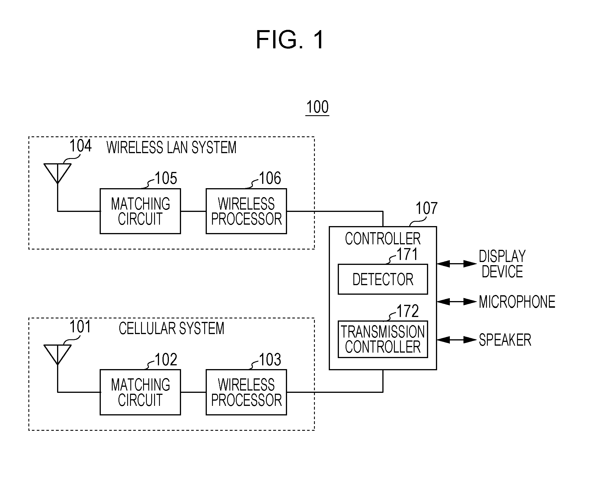
[0026]FIG. 1 is a block diagram showing an example configuration of a wireless mobile device 100 according to the present embodiment.

[0027]The wireless mobile device 100 shown in FIG. 1 is, for example, a wearable wireless device, such as a watch-type terminal as shown in FIG. 2, which is used with it mounted on the body of the user.

[0028]The wireless mobile device 100 shown in FIG. 1 includes, for example, two wireless systems: a cellular system and a wireless LAN system (e.g., a WiFi® system).

[0029]In the present embodiment, it is assumed that priorities are assigned to the cellular system and wireless LAN system. In the present embodiment, there will be described an example in which the priority of the cellular system is higher than that of the wireless LAN system.

[0030]The wireless mobile device 100 shown in FIG. 1 includes an antenna 101, a matching circuit 102, a wireless processor 103, an antenna 104, a matching circuit 105, a wirele...

second embodiment

Modification of Second Embodiment

[0074]In a modification of the second embodiment, there will be described a case in which a cellular system uses the unused antenna of a wireless LAN system which is stopping transmission and reception.

[0075]FIG. 5 is a block diagram showing an example configuration of a wireless mobile device 200 according to the present modification. Note that elements that operate in the same manners as do those of the wireless mobile device 100 shown in FIG. 1 are assigned the same reference signs in FIG. 5 and will not be described.

[0076]Specifically, the wireless mobile device 200 includes the elements of the wireless mobile device 100, as well as a switch 201, a matching circuit 202, a switch 203, a switch 204, and a division / combination unit 205.

[0077]One terminal of the switch 201 is connected to the antenna 104, and the other terminals (terminals A, B) are connected to the matching circuit 105 or matching circuit 202. The switch 201 connects the one termina...

third embodiment

[0091]A wireless mobile device of the present embodiment has the same basic configuration as that of the wireless mobile device 100 of the second embodiment and therefore will be described with reference to FIG. 1.

[0092]FIG. 7 is a flowchart showing the operation of a wireless mobile device 100 according to the present embodiment. Note that steps similar to those in the second embodiment (FIG. 4) are given the same reference signs in FIG. 7 and will not be described.

[0093]In the present embodiment, an operation using a wireless LAN communication is, for example, a download of data from a Web site.

[0094]In the present embodiment, as in the first embodiment, there will be described a case in which the priority of a cellular system is higher than that of a wireless LAN system.

[0095]In FIG. 7, if it is determined that the state in which the user is taking a voice call is the close-to-head state (ST105: YES), a controller 107 of the wireless mobile device 100, in ST301, causes the cellul...


PUM


Abstract

A wireless mobile device is used with the wireless mobile device mounted on a body of a user and includes a first wireless processor that performs wireless signal processing on a signal for a data communication in a first wireless system, a second wireless processor that performs wireless signal processing on a signal for a voice call in a second wireless system having a higher priority than a priority of the first wireless system, and a controller that, when a data communication in the first wireless system and a voice call in the second wireless system occurred at the same time, in a close-to-head state in which the wireless mobile device is brought close to a head of a user, reduces transmission power with which the first wireless processor outputs a transmission signal.

Description

BACKGROUND[0001]1. Technical Field[0002]The present disclosure relates to a wireless mobile device, such as a wearable device, and a transmission method.[0003]2. Description of the Related Art[0004]The use of smart devices typified by smartphones has rapidly spread in recent years. In particular, wearable devices are attracting attention as downsized, advanced smart devices. Watch-type terminals having a short-range wireless communication function and used in association with smart phones and wireless mobile terminals having a cellular communication function have already been commercialized.[0005]Commercializing wearable devices requires downsizing antennas. However, downsizing a wearable device results in a size reduction of a circuit substrate included in the wearable device, an increase in the antenna current distribution density of the circuit substrate, and an increase in the specific absorption rate (SAR) value. Typically, it is difficult to reduce the SAR of a small terminal....

Claims


Application Information

Patent Timeline
IPC IPC(8): H04M1/725H04W72/10H04B1/3827H04M1/72454
CPCH04M1/72527H04B1/3838H04W72/10H04B1/385H04M2250/06Y02D30/70H04M1/72454
Inventor KOBAYASHI, YUKARIHOSHINO, MASAYUKIUEJIMA, HIROYUKI
Owner PANASONIC INTELLECTUAL PROPERTY CORP OF AMERICA
Learn More